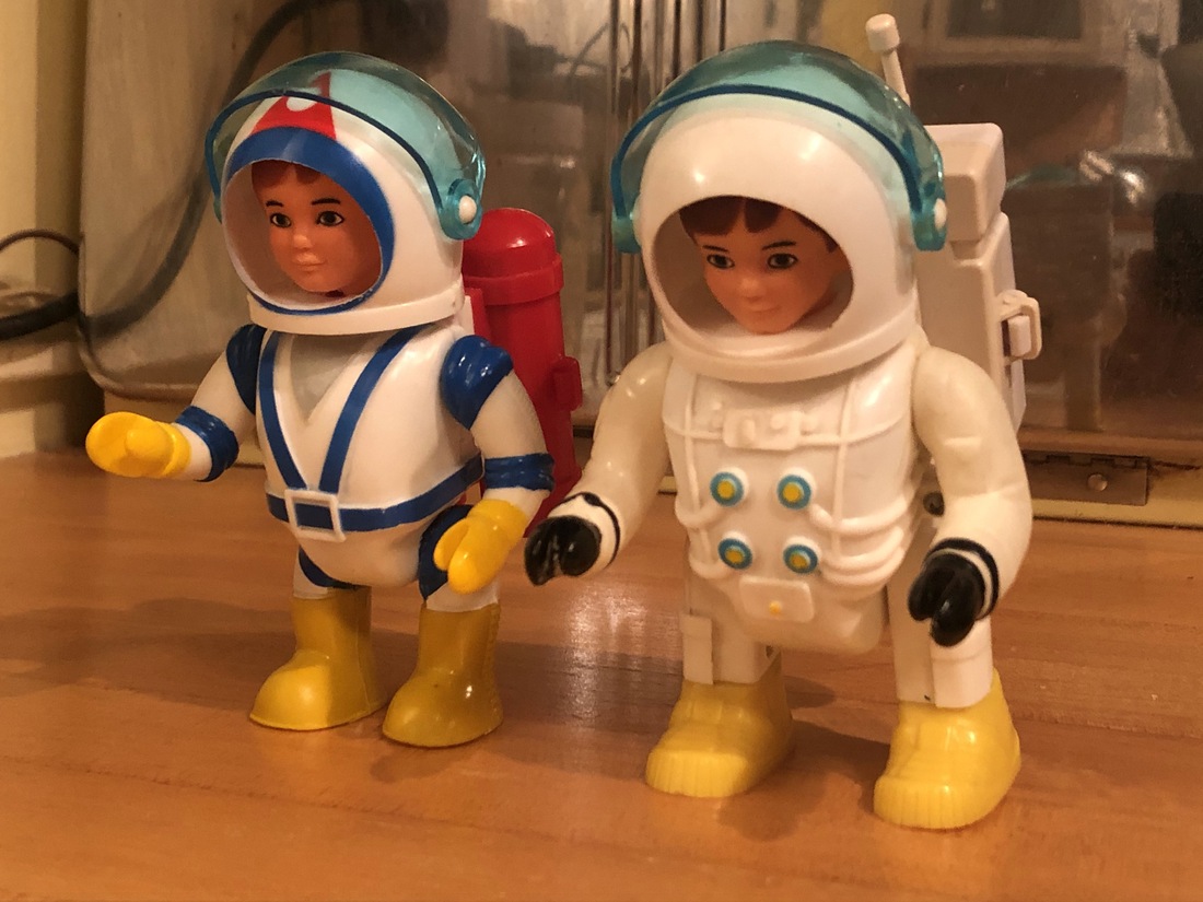
One of my favorite things to do with these toys is see a previously broken one made to work again. I've repaired a number of Billy and Robbie figure and done some other repairs of the vehicles. I also reproduce some of the needed parts.
This page gives detailed directions to repair mainly Robbie and Billy. It's a long page so please use the page links at the top to get around if you need to see one section.
In the repair section I'm listing all of the steps in order as if an entire basket case rebuild/repair was being done. You can use any combination of the repairs with whatever appropriate level of disassembly needed.
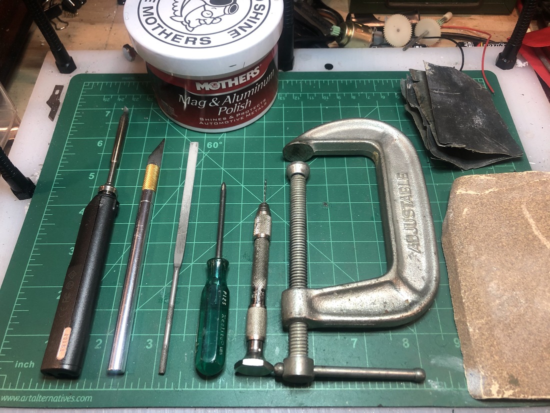
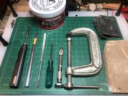
Depending on what repair you need to do, you may not need all of these tools but these would be a minimum to do all of these repairs. I admit that I use some more specialized tools like an arbor press and custom dies I've made on a lathe and/or mill. I do guarantee that all of these repairs can be done with simple hand tools.
- Small phillips screwdriver
- Soldering iron
- Solder
- Hobby file
- Hobby knife
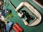
- C-clamp (for pressing operations)
- 100 grit sand paper
- 800 grit sand paper
- Mother's Billet Polish, Brasso or equivalent
- Pin vise (micro drill)
- #74 drill bits
- Plastic glue (if body pieces need repair)
- Dieelectric grease (if motor repair is needed).
- Tubular rivet peening tool (if battery trace rivets are to be replaced)
|
|
Filing/sanding and polishing:
I've removed glue and scratches from opaque or clear plastic with the following process.

- Rough sanding/shaping can be done with an X-Acto knife as a scraper, a small hobby file or 100 grit sandpaper. I scrape with the X-Acto for very high globs of glue and generally prefer the file to keep a surface flat and the sandpaper to blend a curved surface or feather in a spot repair.
- Intermediate sanding with 400 grit works fine for me. I don't find myself needing to step down through too many grits
- Final polishing can be done with many light polish creams. I prefer Mothers Mag and Aluminum Polish all around for metal and plastic. Just apply with a paper towel rubbing it in then cleaning it off with clean section of the paper towel.
- top
Parts I make and sell.
 |
Drive Cleat |
The part at the bottom of the Billy and Robbie figures that mates to the vehicle. |
All Robbie and Billy figures with the exception of the scuba Billy. |
Ebay |
 |
Shoulder Kit |
Replacement shoulder joint for Robbie Robot - Gen 1 and gen 2. This joint is spring tension which makes it a funcitonal upgrade for a loose joint. |
Robbie Robot - all models. |
Ebay |
 |
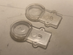
Leg Plates |
Clear leg plates and retaining rings for Robbie Robot. |
Robbie Robot - all models. |
Ebay |
 |
Leg Rods |
Internal plastic rods that move Robbie forward. |
Robbie Robot - all models. |
Ebay |
 |
Clip Ring for Radioactive Retrieval Wagon |
Retaining clip that holds the handle on the Radioactive Retrieval Wagon. |
Radioactive Retrival Wagon - both versions. |
Ebay |
 |
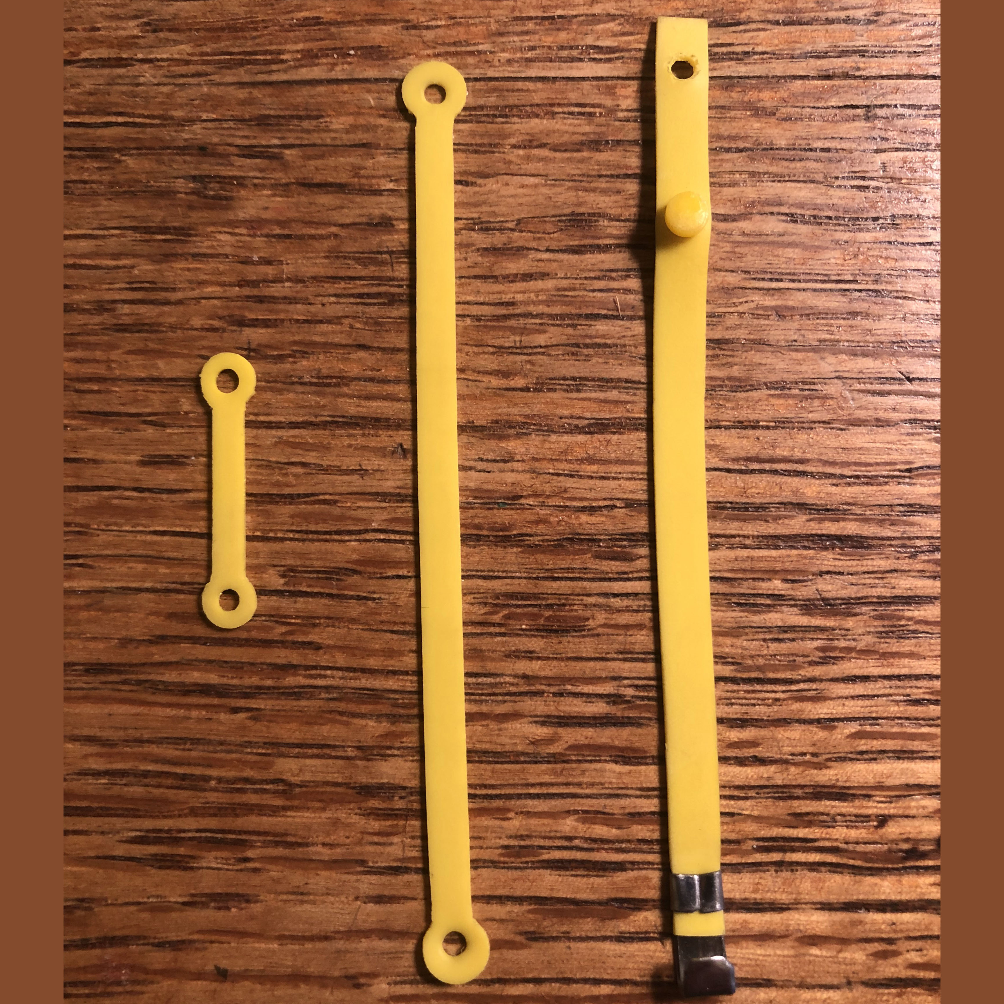
Scuba Scout rubber strap kit |
Rubber strap kit for Scuba Scout. Includes straps for belt, mask and accessory plug. |
Scuba Scout Jet Pack - all versions. |
Ebay |
 |
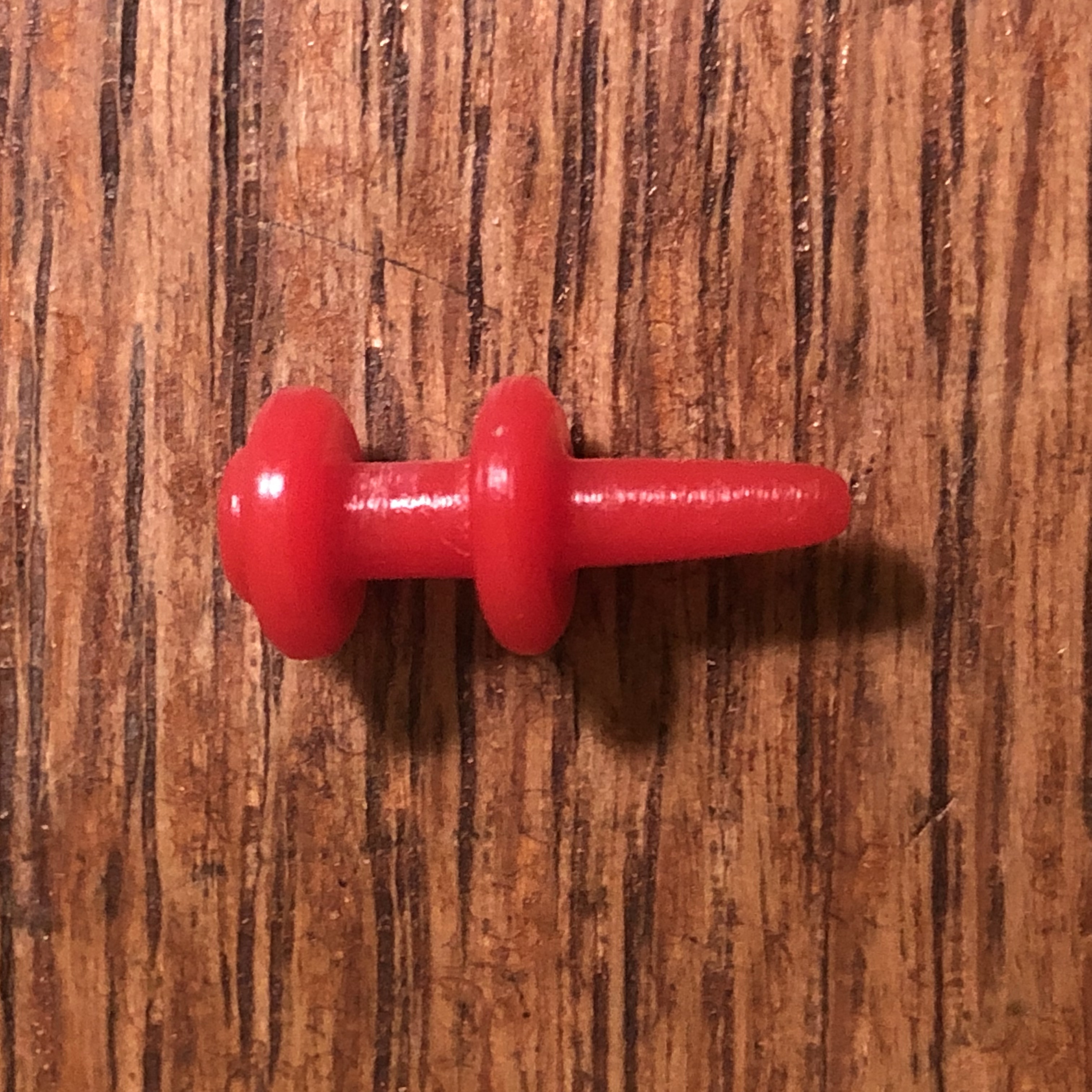
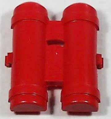
Accessory plug for Scuba Scout |
Reproduction accessory plug for Scuba Scout. |
Scuba Scout Jet Pack - all versions. |
Ebay |
 |
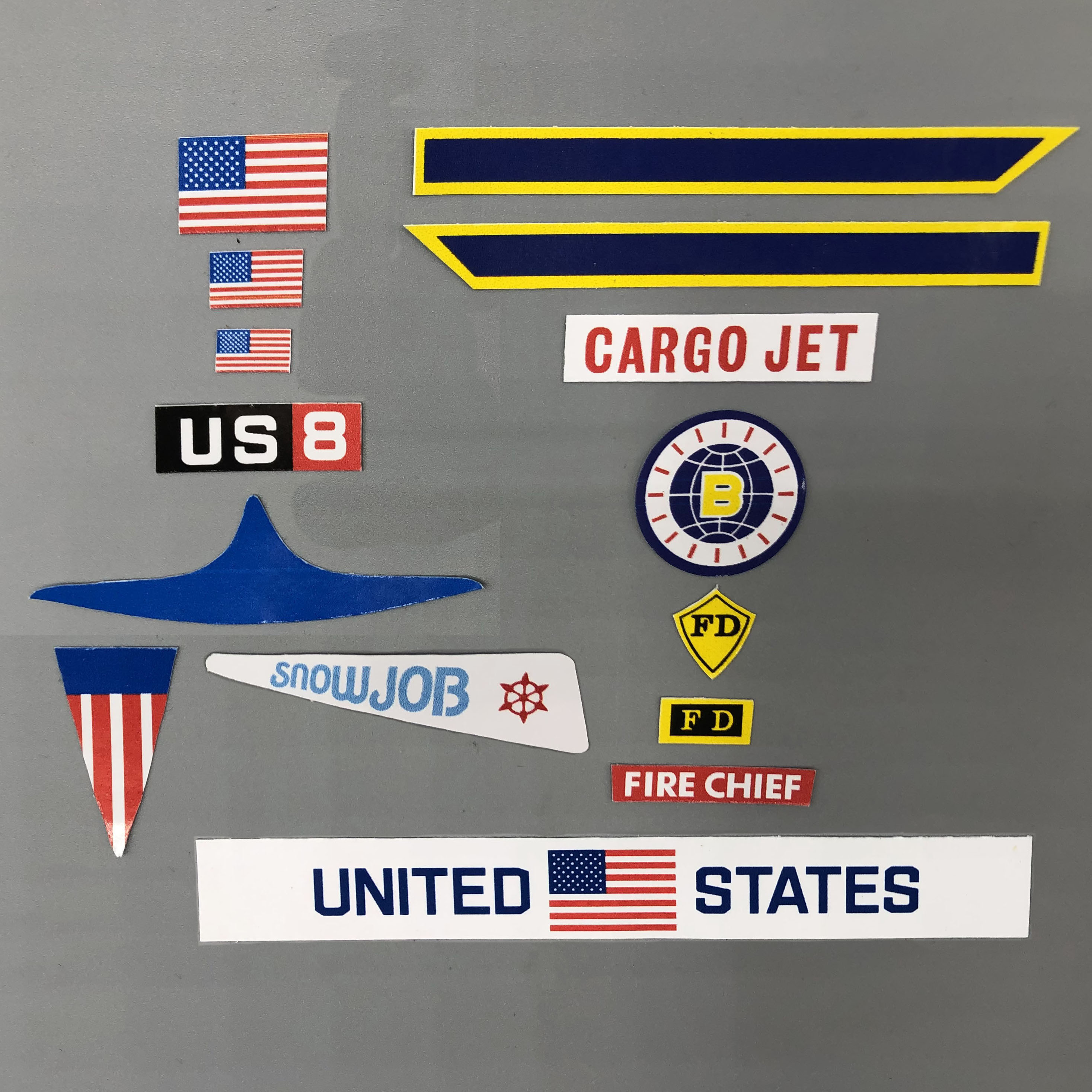
Stickers |
Reproduction stickers for many toys. |
Walking Billy, Space Saucer, Space Car (gen 2), Space Capsule, Radiation Truck (gen 2), Lunar Crawler (gen 2), Exploration Tractor (gen 2), Walking Vehicle, Grabber (gen 1 and gen2), Cargo Jet, Ladder Truck, Hoist Truck, Fire Chief Car, Fire Hat, Snowmobile. |
Ebay |
 |
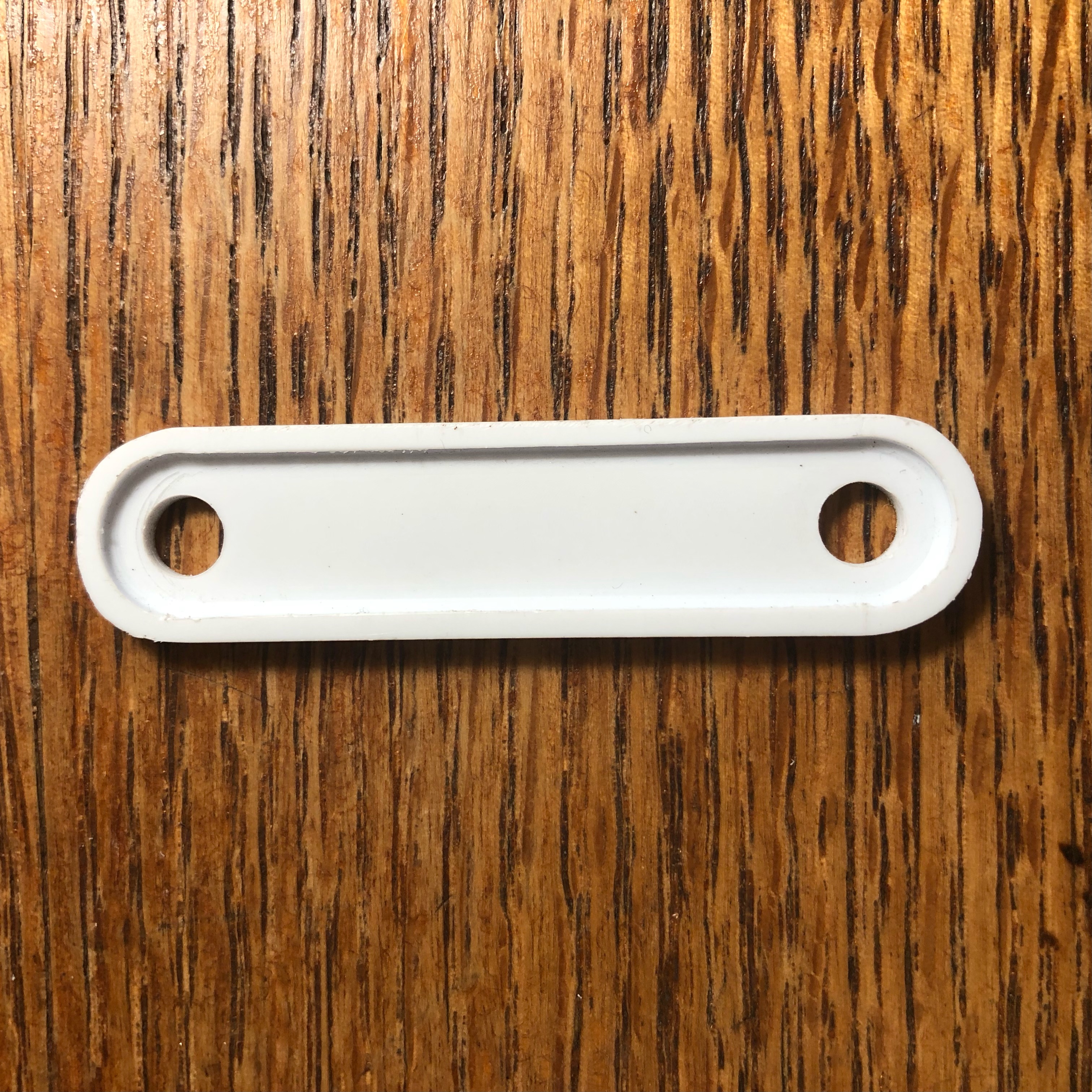
Tow Bar |
Reproduction tow bar for Space Base sets. |
Space Base set. |
Ebay |
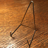 |
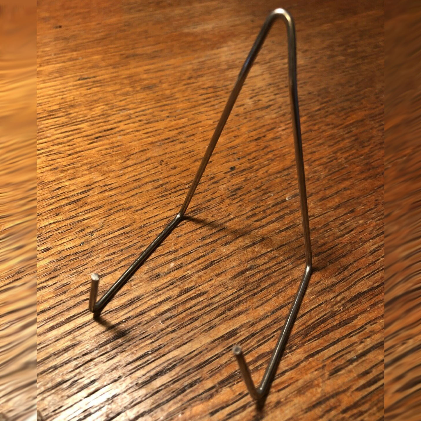
Flying Device Door Hanger |
Reproduction flying device door hanger for Space Base and Deluxe Space sets. |
Space Base set, Deluxe Space set. |
Ebay |
Other parts, supplies and tools for sale.
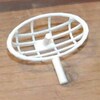 |
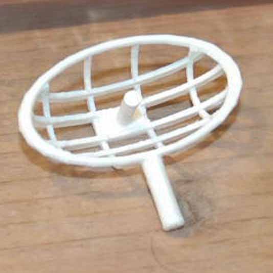
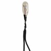
White Antenna |
3D printed white replacement antenna for Robbie Robot. Have used these. They are nicely done. The post is a bit long and the post hole just a bit too big for Robbie to you'll want to modify it just a bit. Not a major issue at all. |
Robbie Robot - all models. |
Ebay |
 |
White Antenna |
White replacement antenna for Robbie Robot. This one looks to be molded plastic but I'm not sure. A bit more expensive than the 3D printed one above. |
Robbie Robot - all models. |
Classic Tin Toy |
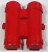 |
Pack Cover |
Replacement pack cover for Robbie Robot gen 1. From the listing I'm not sure if this also fits Billy Gen 1. I ahve noticed a slight difference in the gen 1 pack covers. |
Robbie Robot - Gen 1. *Maybe* Billy gen 1 as well. |
Classic Tin Toy |
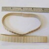 |
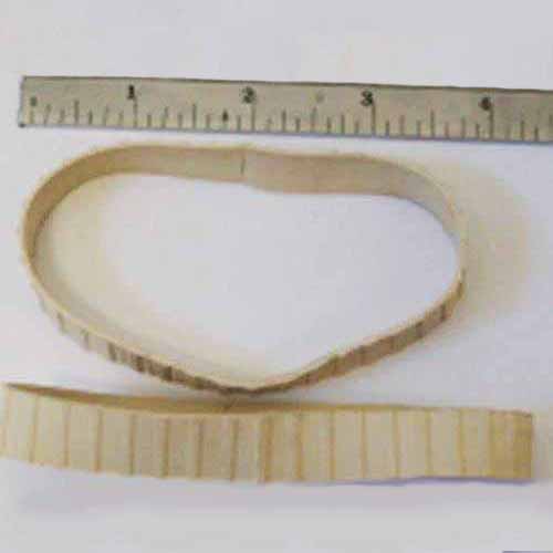
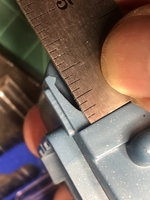
White Tractor Tread |
White replacement treads for Space Tractor. There are two listings for white treads. The first says 8-3/4" x 3/4" although the picture withe ruler seems to show a 1/2" width which would be a correct fit. The second says 9" x 1/2" which would be the right width but probably a little loose. |
Space Tractor - gen 1 and gen 2. |
Classic Tin Toy 1 (8-3/4" x 3/4")
Classic Tin Toy 2 (9" x 3/4")
|
 |
10 Tooth Gear |
10 tooth gear for Robbie drive shaft. This gear goes on drive shaft right above the drive cleat. |
Robbie Robot - all models. |
Amazon |
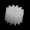 |
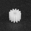
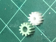
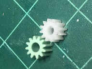
12 Tooth Gear |
12 tooth gear for vehicles. |
Motor gear in figures and used in some of the vehicles. |
Amazon |
 |
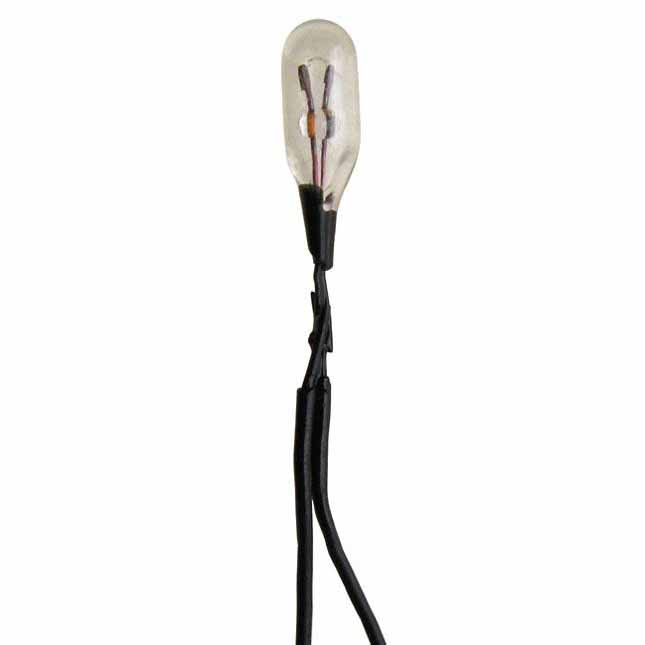
1.5V Bulb |
1.5V grain of wheat bulb. |
Robbie Robot - all models. Lighted accessories. |
All Electronics |
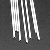 |
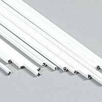
1/16" plastic coated wire |
1/16" plastic coated wire. Plastruct# PLS90102 |
For repairing mounting post in Billy (gen 1) |
Hobby Linc |
 |
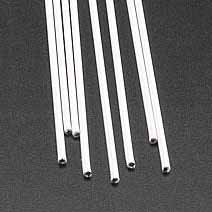
3/64" plastic coated wire |
3/64" plastic coated wire. Plastruct# PLS90101 |
For repairing leg plate post in Robbie |
Hobby Linc |
 |
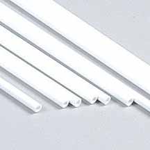
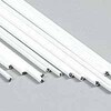
1/8" plastic tubing |
1/8" tubing wire. Plastruct# PLS90604 |
For fixing 3D printed Robbie Robot antennas. |
Hobby Linc |
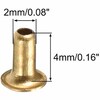 |
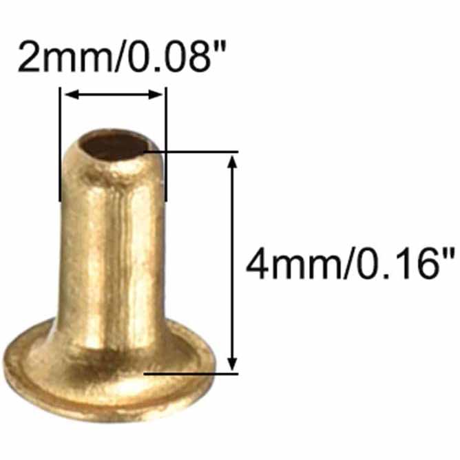
2mm x 4mm tubular rivets |
2mm x 4mm tubular rivets |
For repairing battery traces. |
Amazon |
 |
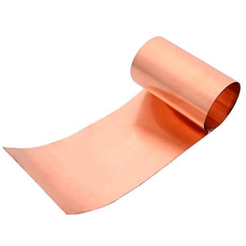
.2mm thick copper sheet |
.2mm thick copper sheet |
For making new battery traces. |
Amazon |
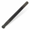 |
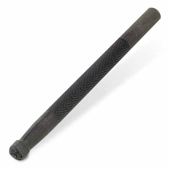
Tubular rivet peening tool. |
Tubular rivet peening tool. |
For repairing battery traces. |
Amazon |
- top
- top
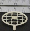
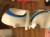
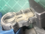
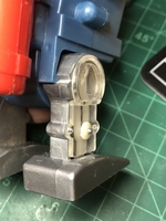
- Remove visor. Try not to stress the smallest ends of the visor as they may break. Best to apply leverage on the larger part of the visor just before the hole starts.
- Remove two screws at the back.
- Remove front body plate.
- Remove arms and legs.
- Remove face.
- Unsolder motor.
- Remove gears.
- Remove Jet Pack
- Remove drive shaft.
- top
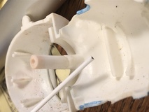

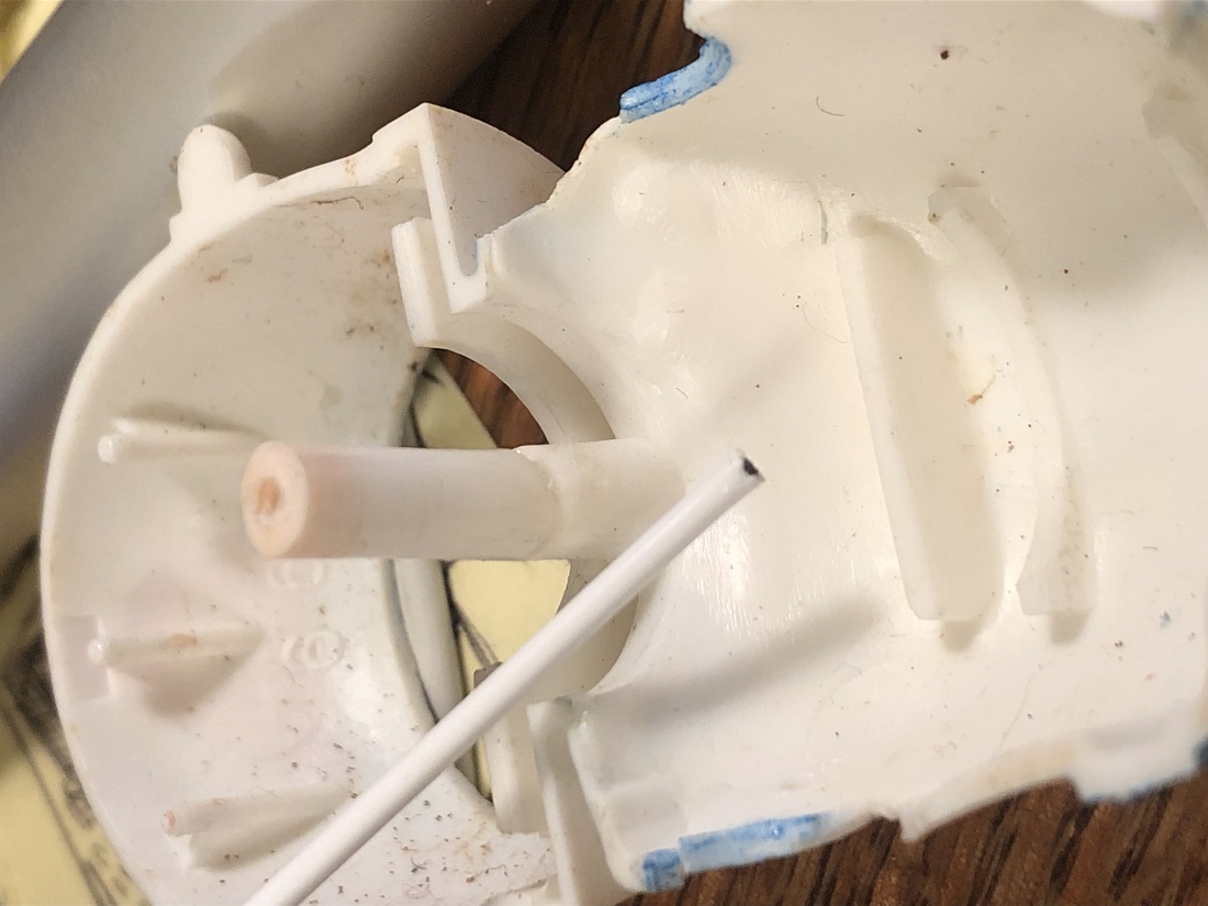
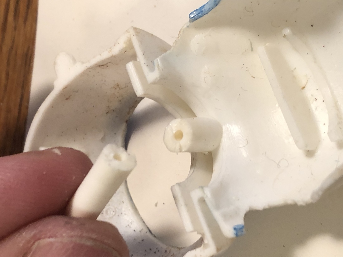
The post that the top screw attaches to is often broken. Luckily there is already a hole in this post for a reinforcing rod. I like to use the 3/64" Plastruct plastic over metal for strength and the ability to glue it to the body part.
- Get to know how the broken pieces fit together.
- Test fit the rod to the body and broken post piece. Make sure it can fit into each at least 1/8".
- If needed drill out the hole on either side.
- Cut the rod to a length short enough that the pieces can be joined.
- Apply some liquid plastic glue to the hold in the body.
- Insert the rod into the hole in the body and allow to dry a few minutes.
- Position the post in your hand so that you know exactly how it will fit onto the body.
- Apply liquid glue to the hole in the post.
- Quickly push the post on the rod and position correctly on the body.
- Apply a little more glue and let the entire assembly dry at least 10 minutes.
- top


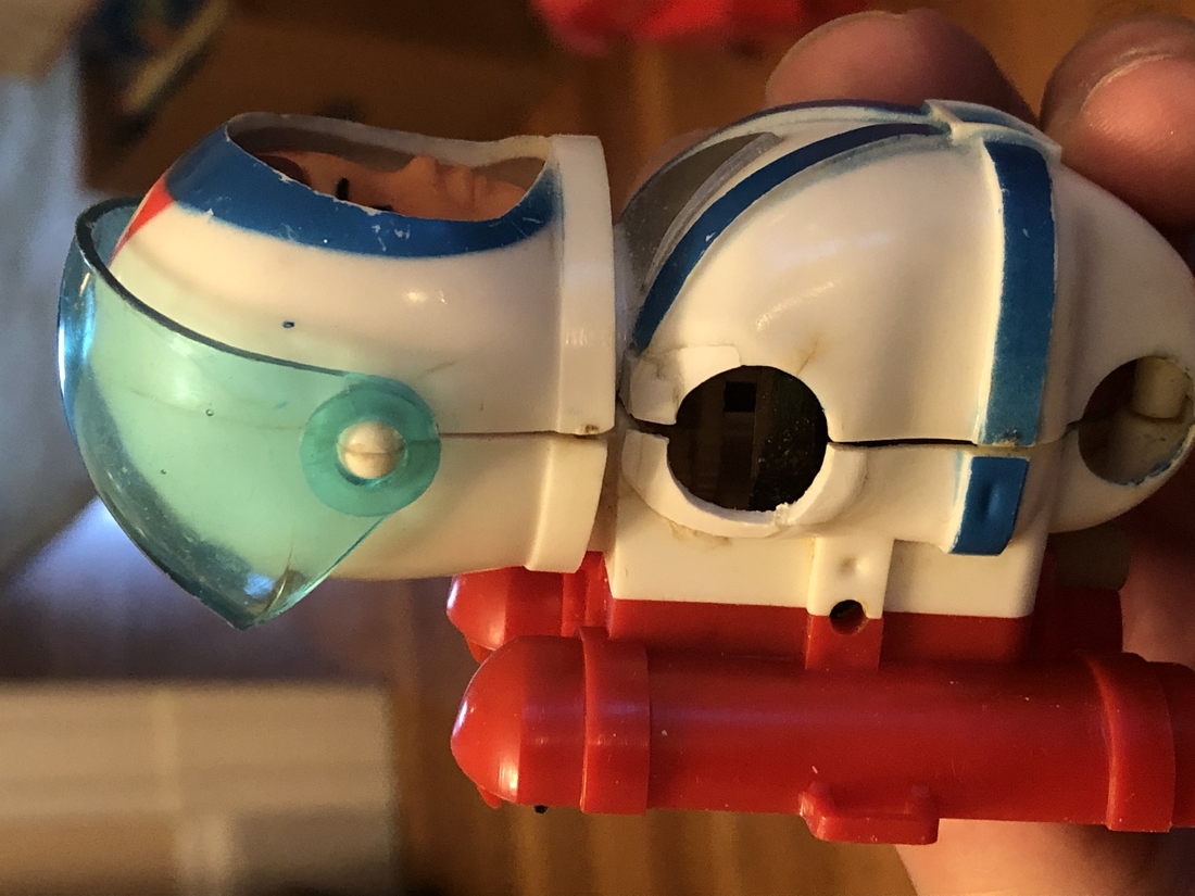
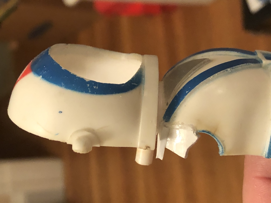
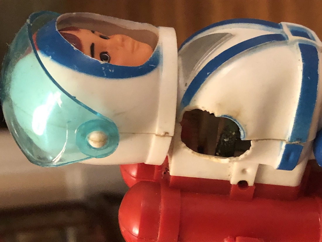
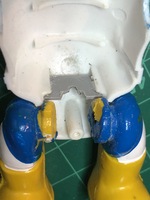
The body pieces on Billy are often broken at the shoulder joints. As bad as they look they can actually be fixed with some styrene, glue and a bit of time with a file shaping the repair. Mainly you just need to cut a small piece of sheet styrene to fit into the broken area and glue it in. It may take more than one piece. Make sure to let it dry pretty solid before shaping with a small file. I use a flat file for the outer shaping and a rounded one for the arm sockets. It can take some time but the end result is worth the effort. Once you're happy with your repair and the fit of the arms, smooth the repair out with some 400 grit sand paper and final polish with your fine polish.
- top
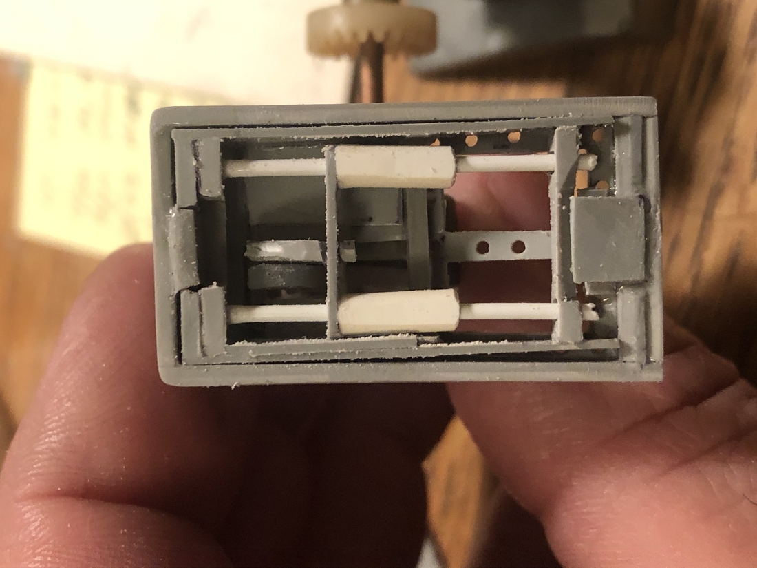
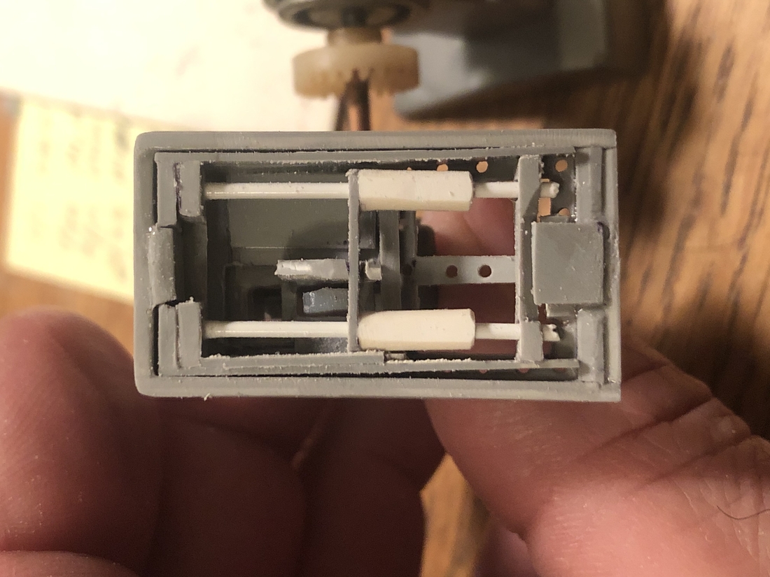
The first generation Billy sometimes needs a little repair work to stand on his own. This can be a little tricky and free-form but basically you want to create new stops from sheet plastic and glue them into the body piece. I've found te best way is to create a single piece for both, glue it in then shape it in place to adjust for the stance and to allow the motor to clear. Being patient and letting the glue dry completely is pretty key here.
- Cut a piece of sheet plastic to fit between the two original stops that comes out just a bit.
- Hollow out the center so that the bottom of the motor will clear this piece.
- Fit Billy back together using a rubber band to hold him togehter.
- install batteries.
- Test standing.
- If he is leaning too far forward, dis-assemble and file back the new stops just a bit.
|
|
- top
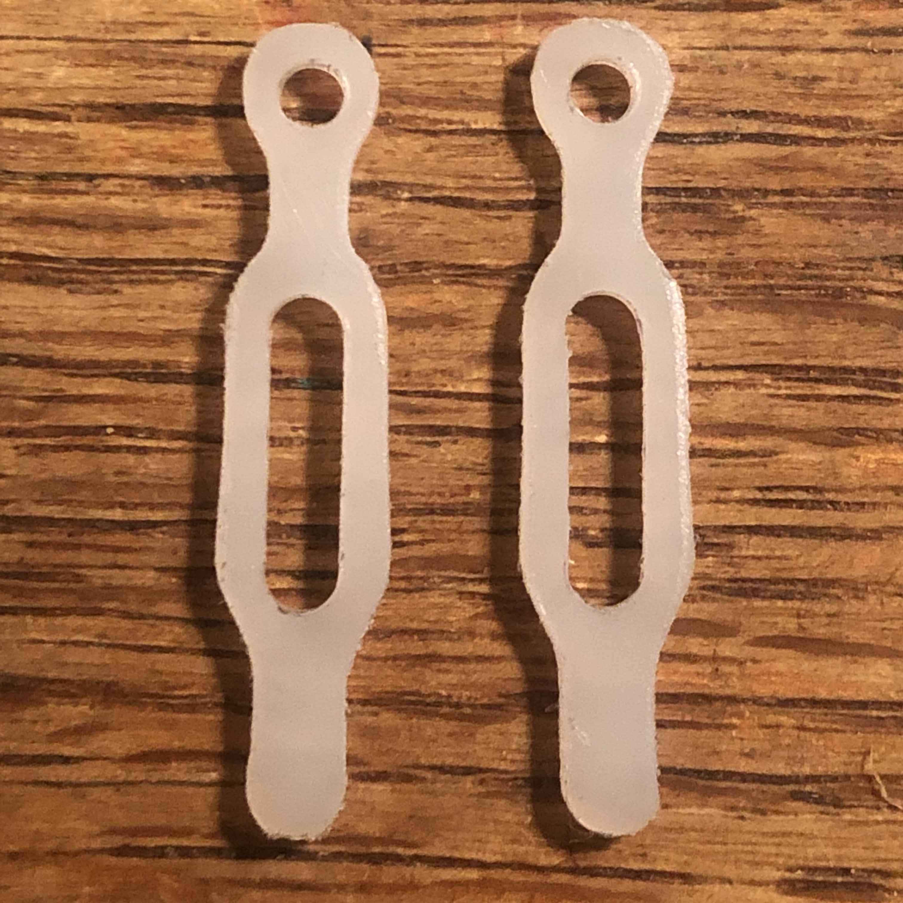
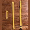
Fixing the leg supports for the walking Billy is the same process as for Robbie. Please use the instructions here taking into account that the Billy gen 2 leg support is a little longer and wider than Robbie's support and, of course is white.

- top
- Install drive shaft.
- Install Jet Pack
- Solder motor.
- Install face.
- Install legs.
- Install arms.
- Attach front body plate.
- Install two screws at the back.
- Install visor. Again, careful not to snap off the outside pieces.
- top
- top
Make sure you have the right size smaller screwdriver and a container to stash the small parts.
- Remove the antenna.
- Remove the three screws that hold the body together and remove the front body panel and legs, arms and visor.
- Disassemble legs (not gear and axle though) by carefully prying the retaining rings off of the clear leg plates. Be careful here since they can flick off and disappear forever!
- Unsolder the motor and mark the front side with a sharpie so you know which side is which. Don't want Robbie doing the moon walk! Well maybe...
- Unsolder the motor and remove it along with the bulb.
- Remove any excess solder from the leads since they will need to fit through a slot.
- Remove the gear box.
- Remove the two screws holding the Jet Pack on and remove the Jet Pack.
- Give everything a wash with dish or hand soap. Don't use anything solvent based like brake cleaner or thinner since it can corrode plastic.
- top
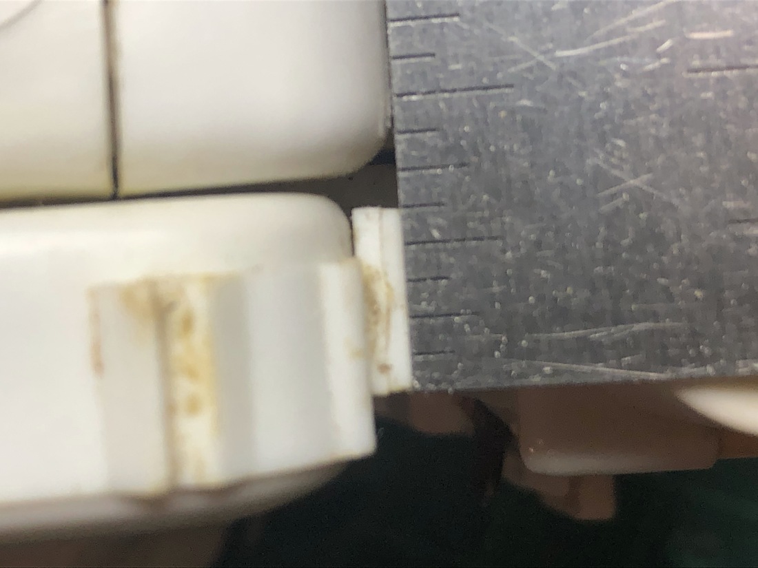
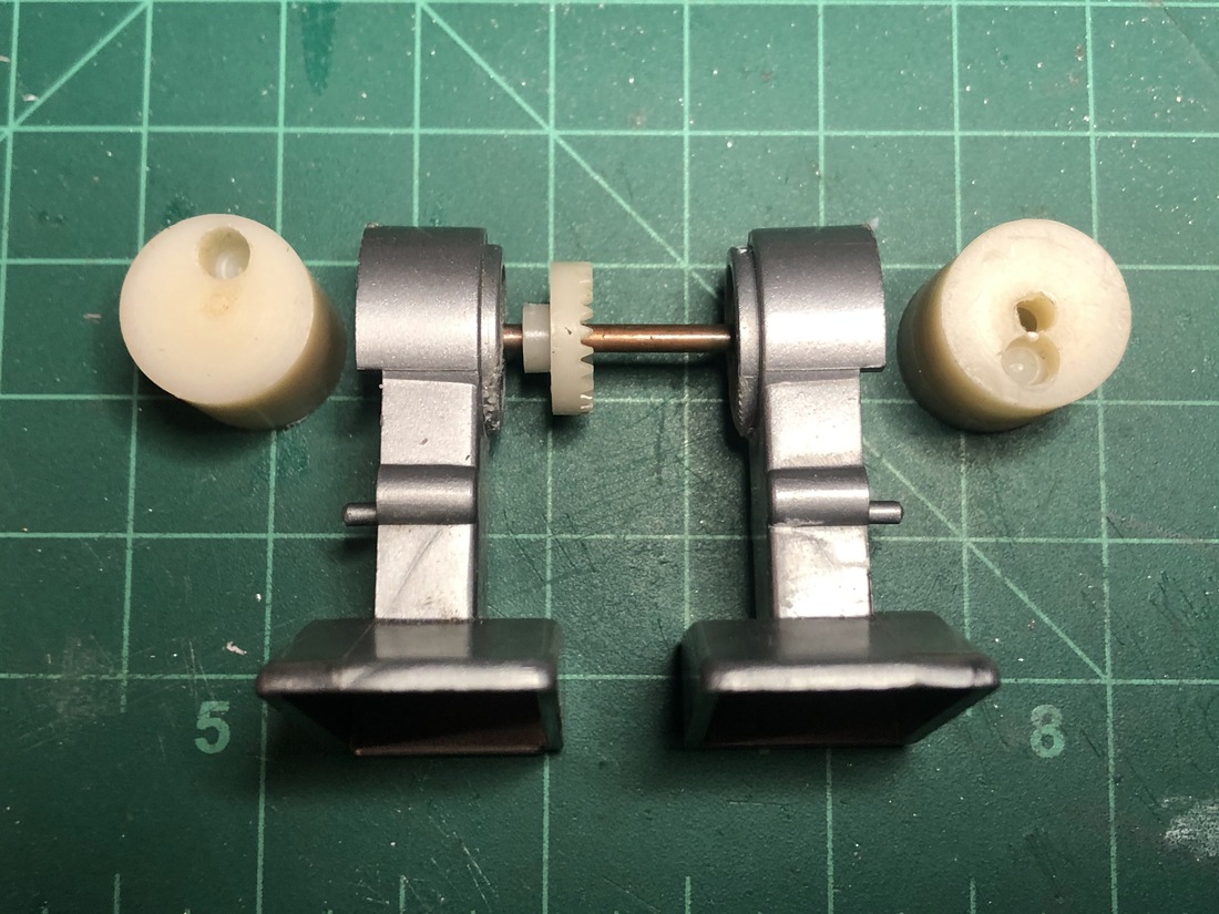
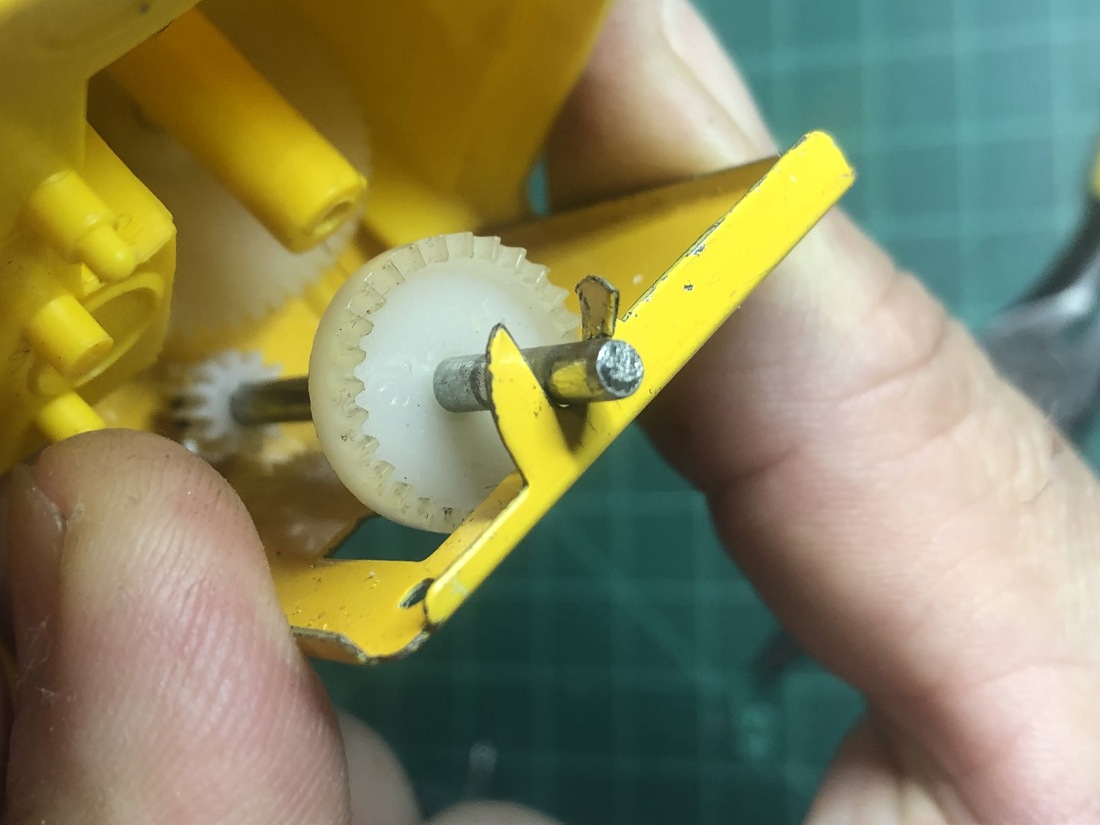
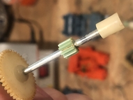
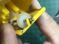
This is the most common repair I've done. I think all but one of the robots I've repaired needed this. The issue is that the drive gear being the smallest in the system is pressed on to a metal rod and over the years goes brittle and snaps from stress. The telltale signs are that the motor runs but the walking mechanism is either not working or flakey.
When doing this replacement I like to give the drive axle a little shine as well. This is also an ideal time to replace the drive cleat if needed although no disassembly would be needed if this was the only repair to be done.


Part description
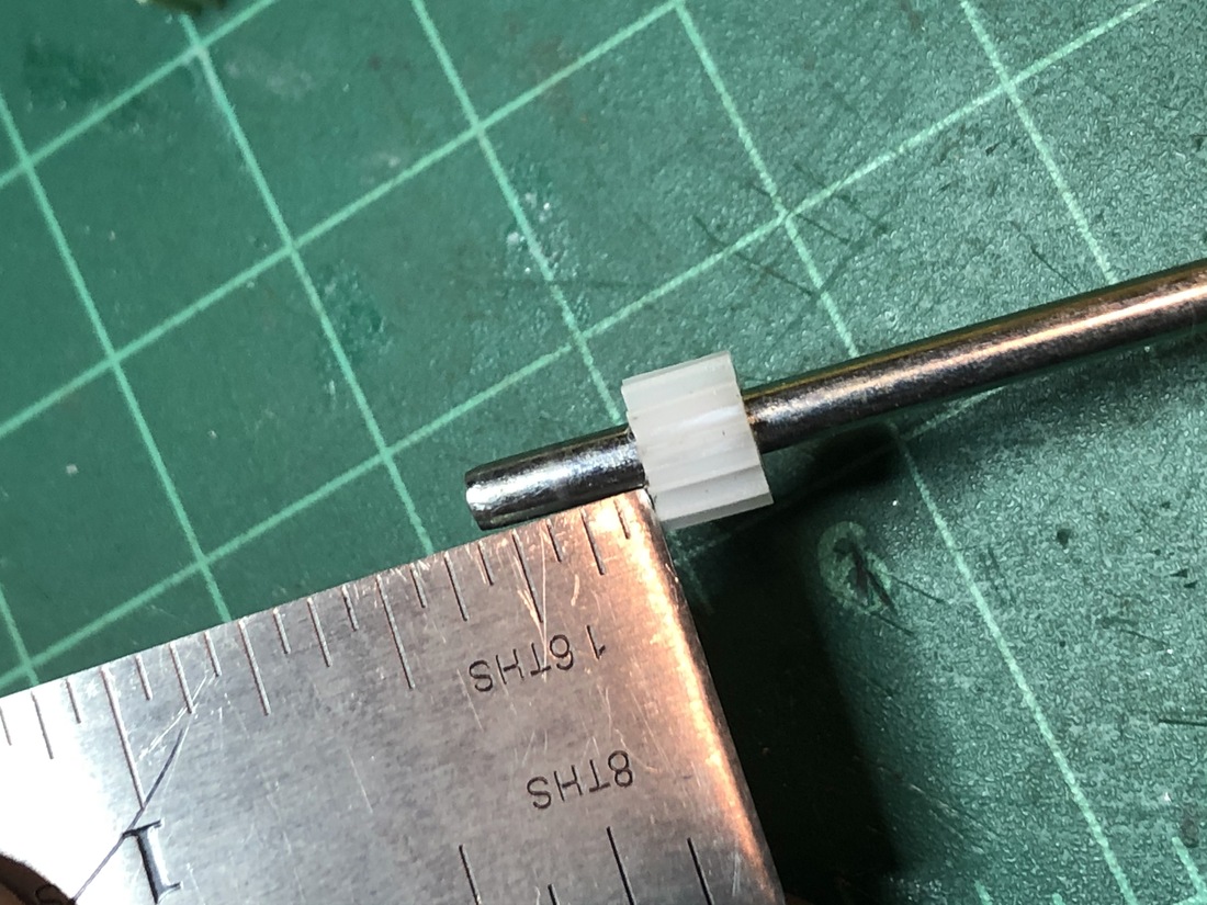
The gear to be replaced is a 12 tooth plastic gear. These gears are available online - usually in fairly large quatities. I've had to drill them out with a 3/32 bit.
Steps
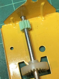
- Confirm that the small green gear on the antenna shaft is loose.
- Remove the drive cleat on the bottom end of the antenna shaft.
- Remove the small green gear from the antenna shaft.
- If the drive axle is corroded give it a little sanding with 400 grit sandpapaer and finish off shining with a fine polish like Mother's Metal Polish or Brasso.
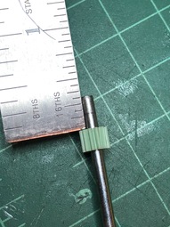
- Install the replacemnent gear on the antenna shaft leaving 10mm of the shaft showing.
- Install the drive cleat making sure that the shaft doesn't come all the way through.
- top
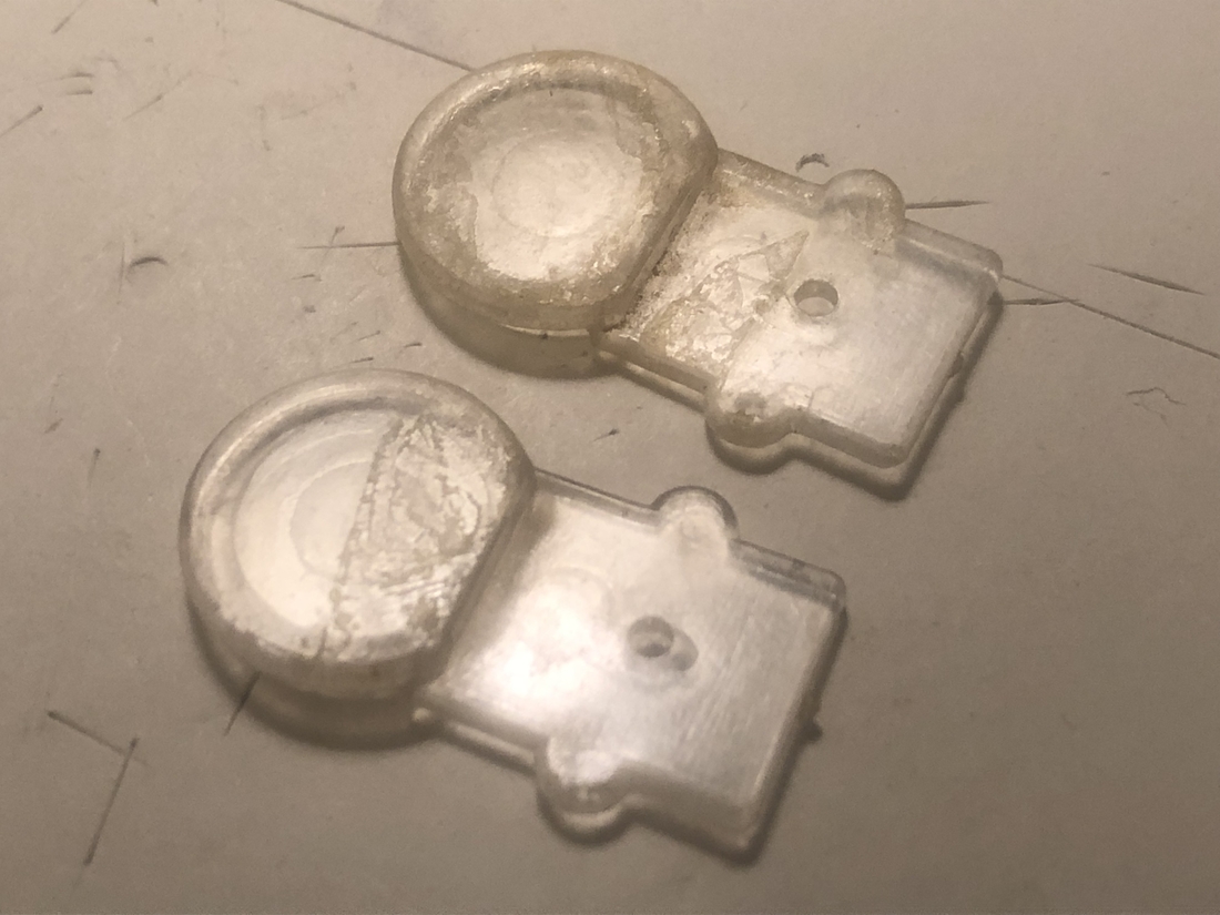
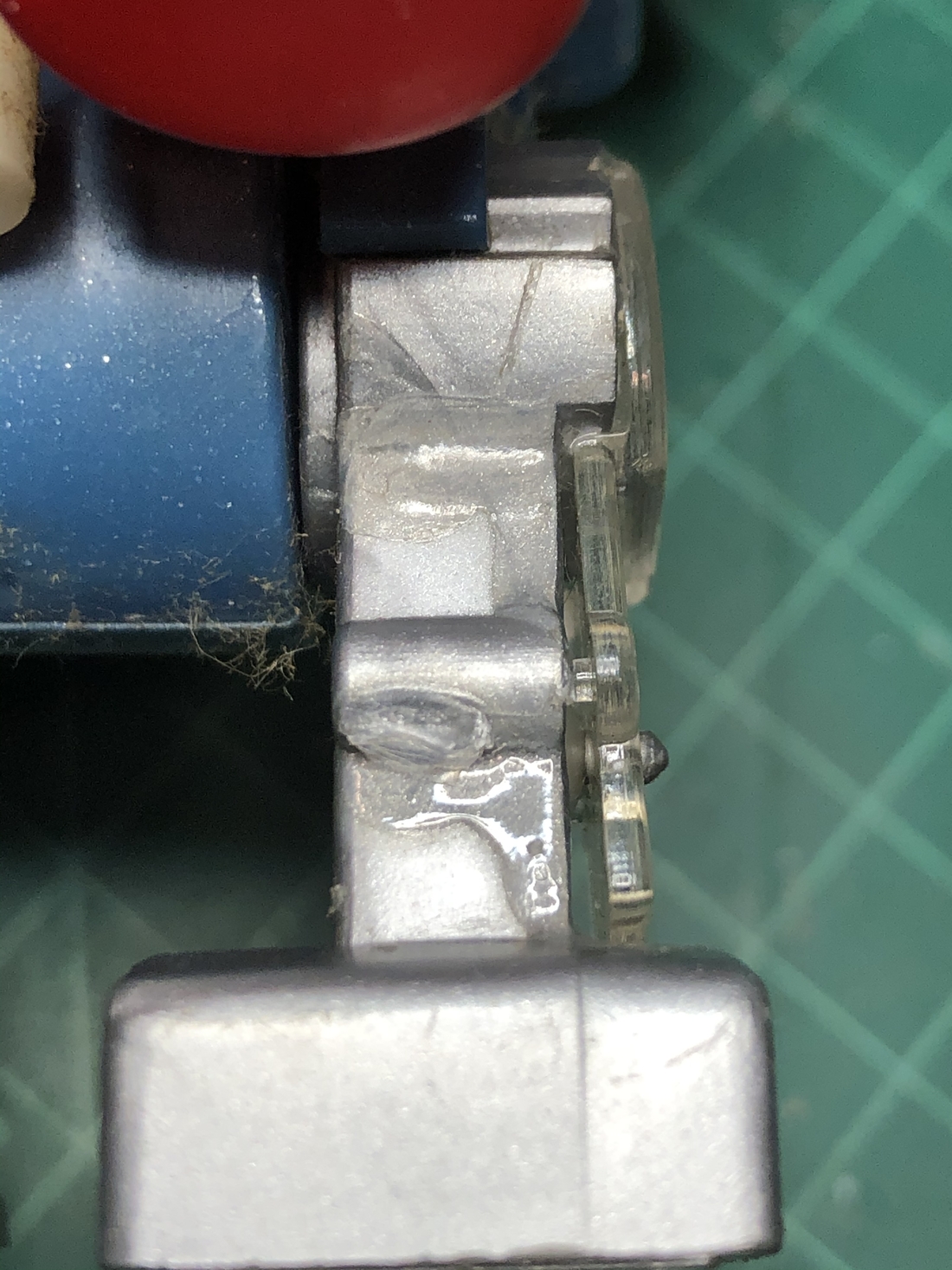
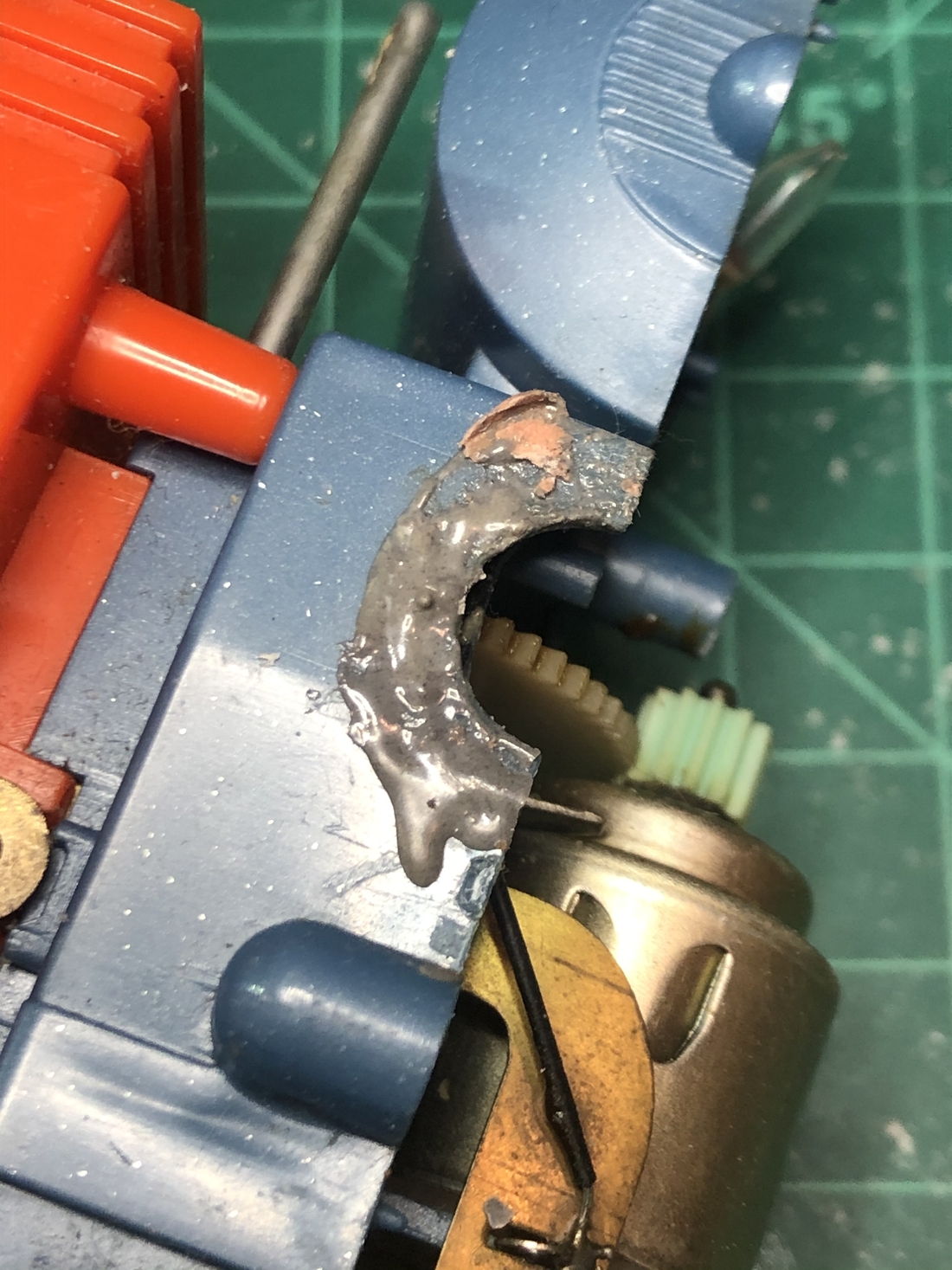
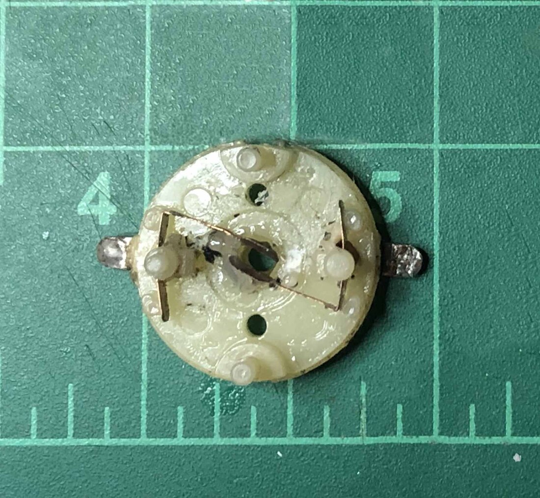
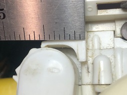
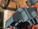
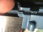
For the body pieces I've mainly washed and removed glue from failed repairs. Luckily the glue I've encountered hasn't been too corrosive to the plastic and has cleaned up well. After disassembly, and cleaning, if there is any repair to do on the body parts use the instructions above to remove the glue or other issue then repair the finish with lighter grade sandpaper and finally some fine polish.

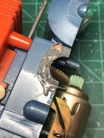

This leg plate was actually glued on over the retaining ring. That's a head-scratcher. This gob of glue on the body actually came off pretty easily since it wasn't a plastic based glue that would have melted the plastic.
- top
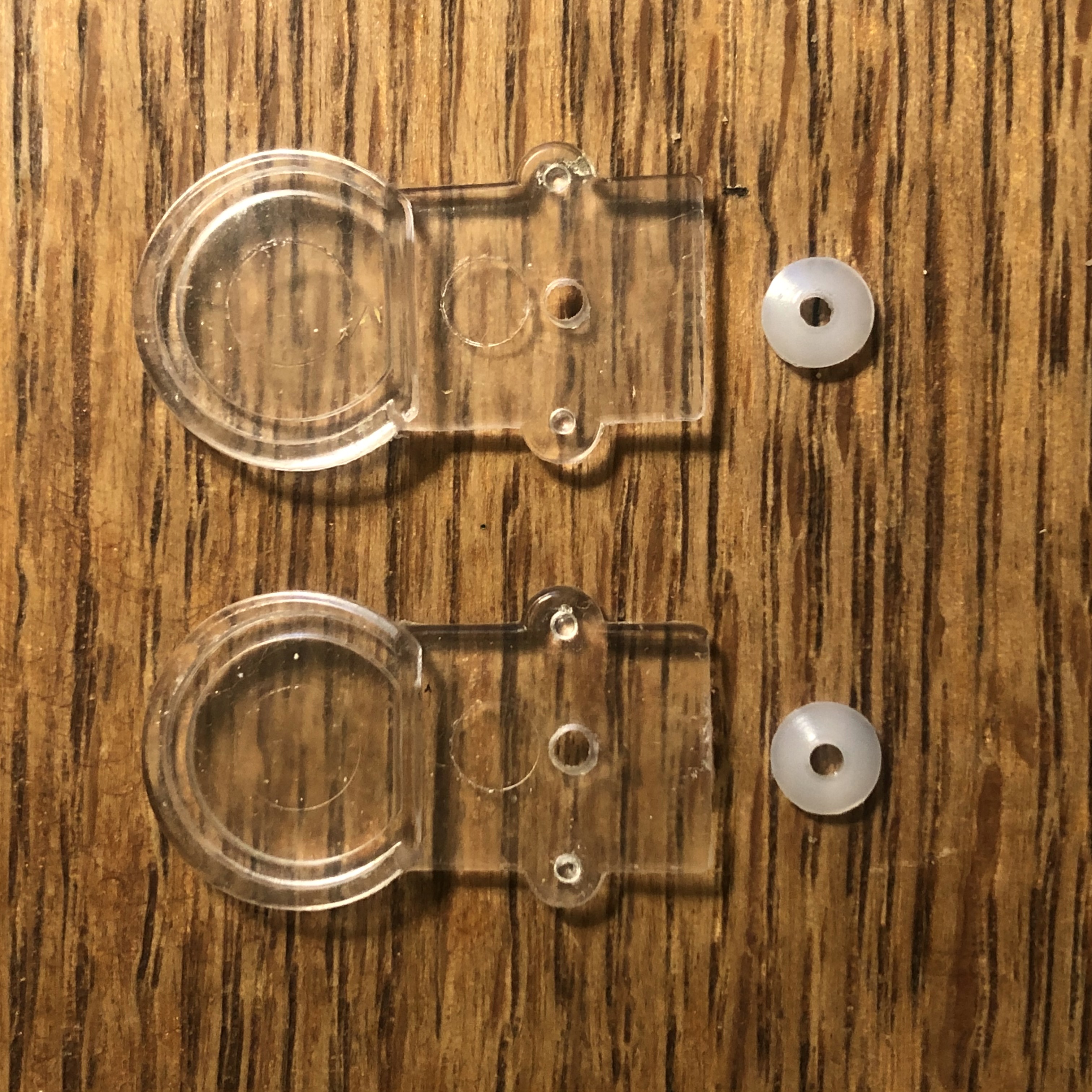
Replacing the leg plates and movement rods are very straightforward. I make reproduction parts of all of these pieces and sell them on eBay (see above).
- Slip the movement rod in from the side.
- Place the clear plate over the movement rod.
- Press the retaing ring over the peg.
- Repeat for other side.
- top
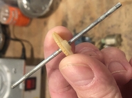
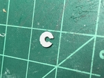
I have encountered a couple broken leg pegs that needed fixing. Plastruct makes these really handy plastic coated rods for model making that makes for an excellent fix. Remove some of the plastic and you have a solid metal rod that can be used to anchor the new piece to the leg after drilling a small receiving hole. This makes for a very solid fix. The only downside is that the rod (1/16") is just a little smaller than the original (5/64) so I had to make a special retaining ring with a smaller hole.
- Set the center of the hole to be drilled in the broken peg stump.
- Drill about 1/8" in with a #size drill bit.
- File the end of a piece of 1/16" Plastruct rod.
- Cut a little less than o1/8" of the plastic off of the rod.
- Cut the rod so that 1/8" will show once inserted.
- Shape the plastic end of the rod with a small file.
- Apply a small drop of super glue to the hole in the leg part.
- Quickly insert the repair piece into the hole.
- top
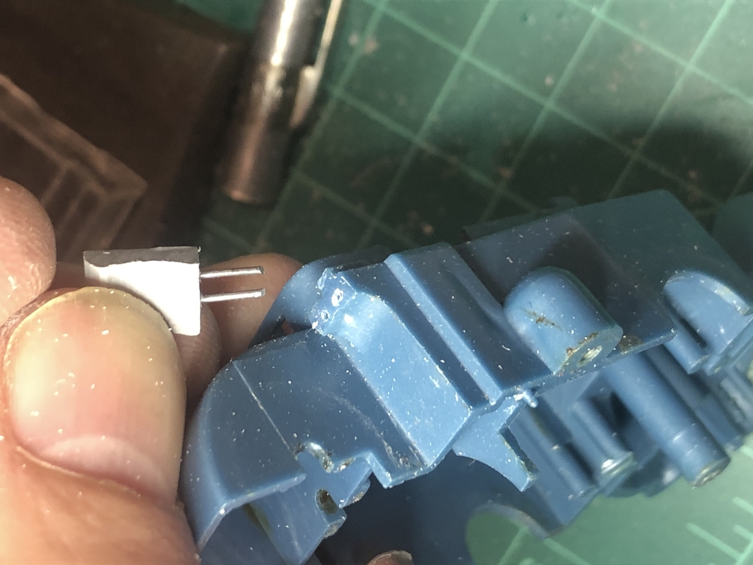
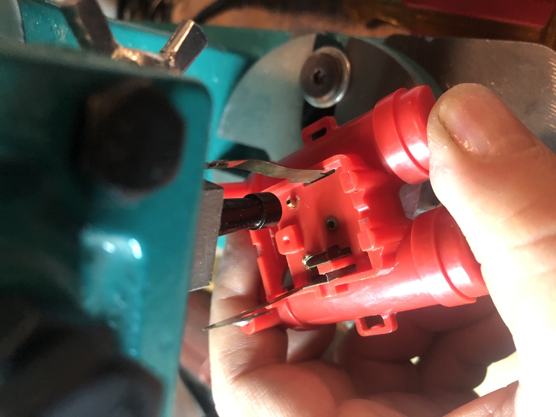
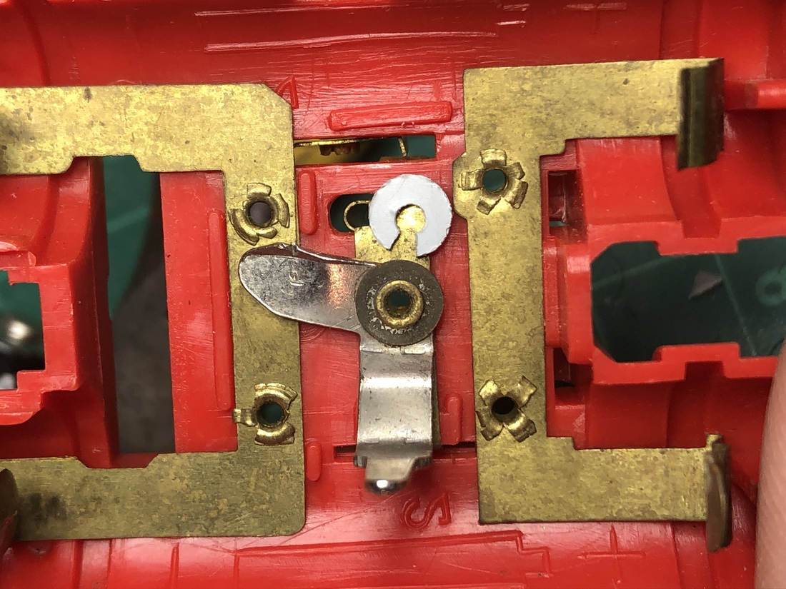
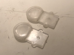
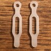
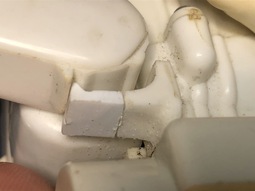
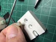
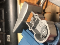
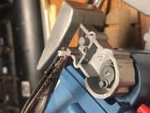
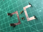
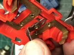
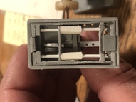
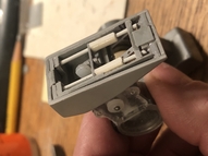
This is probably the most difficult repair and unfortunately is very commonly needed. These little tabs that are supposed to support the legs in either the standing or seated position often break. The fix I do is to make a replacement piece out of sheet plastic, drill two holes and press two thin metal rods in that piece, drill two holes in the body piece then press the replacement piece into the body. The metal rods give the needed strength and flexibility. It can be difficult to drill the holes properly and the pressing operation is tricky without a good way to hold the piece and apply even pressure. I now have hand made jigs to do all of this but I have done it without.
|
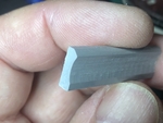
Make the replacement piece
I am not yet selling these pieces as it is still difficult to install them but my arm could be twisted if you wanted to give it a try.
- To make one for yourself start by cutting a 3/8" strip from a 1/8" thick piece of sheet plastic. I use Plastruct plastics for this.
- Once the 3/8" sheet is cut create a similar profile to the original piece using a combination of hand files and/or a dremel tool. I do this on a mill to make many at one time. It's easier to work on the piece before it is cut from the strip.
- Once the profile is cut, set the location for two holes on the bottom of the piece using the hobby knfe to start the hole - 1/16" from the edge for the first and the second 1/8" from the first. Both about 1/16" from the back edge of the piece.
- Then use your pin vise and #74 bit to drill each hole about 3/16" into the piece.
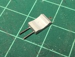
- Cut two 3/8" long pieces of .025" music wire.
- Press each of music wire into the piece.
- Cut the piece off at 1/4".
- Cut the wires of so that about 1/4" remains.
- file and finishe as needed.
|
|
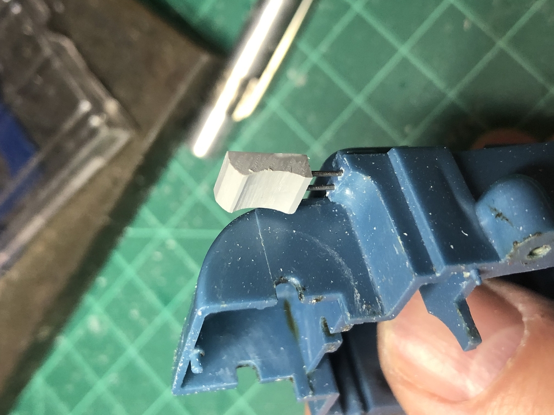
Install the replacement piece


- File down the stub on the body piece so that with the piece installed, there will be 1/2" length from the side feature to the resting point of the new piece.
- Set holes in the stub of the body piece that match the new support piece using the hobby knife.
- Drill the holes into the body with the pin vise and #74 bit. These holes will likely go all the way through.
- line up the new support piece with the body piece and press it in with your hands enought so that it sticks.
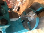
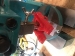
- Now press the new piece all the way in. Before setting up my jigs for the arbor press I was doing this on piece of wood set on the corner of a table. The wood is mainly so that the surface is not too slippery. Holding the body upright with the new part agains the table, push down hard. If you can make something with a slot to hold the new piece as you press it will be a lot easier. That piece slipping while you press is the biggest problem.
- Once pressed in, check that the newly supported leg matches the other one by installing the leg assembly and checking that the legs are at equal angles. If they are not, you can file the edge on the new piece that the leg rests against to allow the leg to come forward a bit more.
- If the new leg support seems too tight, you can bend it back just a bit or file some off. use your best judgement at this point.
- top
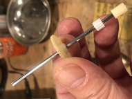
The legs can often become loose on the axle and need tightening. Sometimes so bad that he can't even stand. There are two adjustments to make here.
- Distance from the gear to the leg.
- The overall distance between the legs.
The distance between the gear and it's closest leg should be such that there is just a little wiggle room between them when installed in the body. If there is too much room, the gear presses too hard on the mated gear and introduces drag. This can be adjusted by hand. Just push the gear towards the nearest leg just a bit. It will probably go too far so you can just slowly pry it back with a screwdriver to get it into the right position.
To adjust the overall distance between the two legs, I highly advise making a couple dies to use in a vise or C-clamp to slowly press the one leg along the shaft. Just cut two piece of 5/8" plastic rod or equivalent at about 3/4" long. Drill a 1/8" hole about 1/4" deep in one then an offset hole about 1/8" in both. The one with no center hold goes on the gear side and the one with the hole goes on the non-gear side. This will make it so that only the non-gear side will move.
With your dies created, place them at each end of the axle while laying on a table.
- Set the C-clamp around the entire assembly.
- Tighten the C-clamp to move the legs closer together.
- Test fit body part with the assembly still together.
- Adjust and test as needed until there is just a small amount of wiggle between the legs and body.
|
|
- top
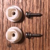
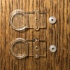
There are a lot of broken or loose shoulder joints out there. Of course I'm partial to the spring tensioned shoulder joint I make. It's much more sturdy than the originals and being spring tensioned, won't come loose. It's simple to swap out the shoulder joint. Just be careful not to break the body part when you insert the arms.
- Remove the old shoulder joints by unscrewing each. Advise setting them aside if you want to maintain the option for originality later on.
- Place the new shoulder joint on each arm and screw on with the small spring on the screw. IMPORTANT: make sure that there is enough room for the new joint to push back into the spring and away from the arm. If you can't flex the new joint back, loosen up on the screw. It's OK to have the screw a little loose. With the spring tension it will not wiggle free.
- top
This should be as simple as just popping the new antenna on and you're done. But... if you buy one of the 3D printed antennas above you'll find that the mounting hole is a bit bigger than it should be and does not fit snug on the drive shaft. You can fix this by simply adding a piece of tape on the drive shaft or filling the hole with a new piece of plastic and re-drilling. This is what I've done to modify the 3D printed antennas:
- Carefully drill out the center hole with a #29 drill bit.
- Glue and press in a piece of Plastruct 1/8" hollow rod.
- Drill with a #36 bit 3/8" deep.
- Press onto drive axle.
- top
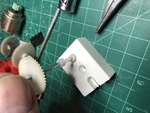

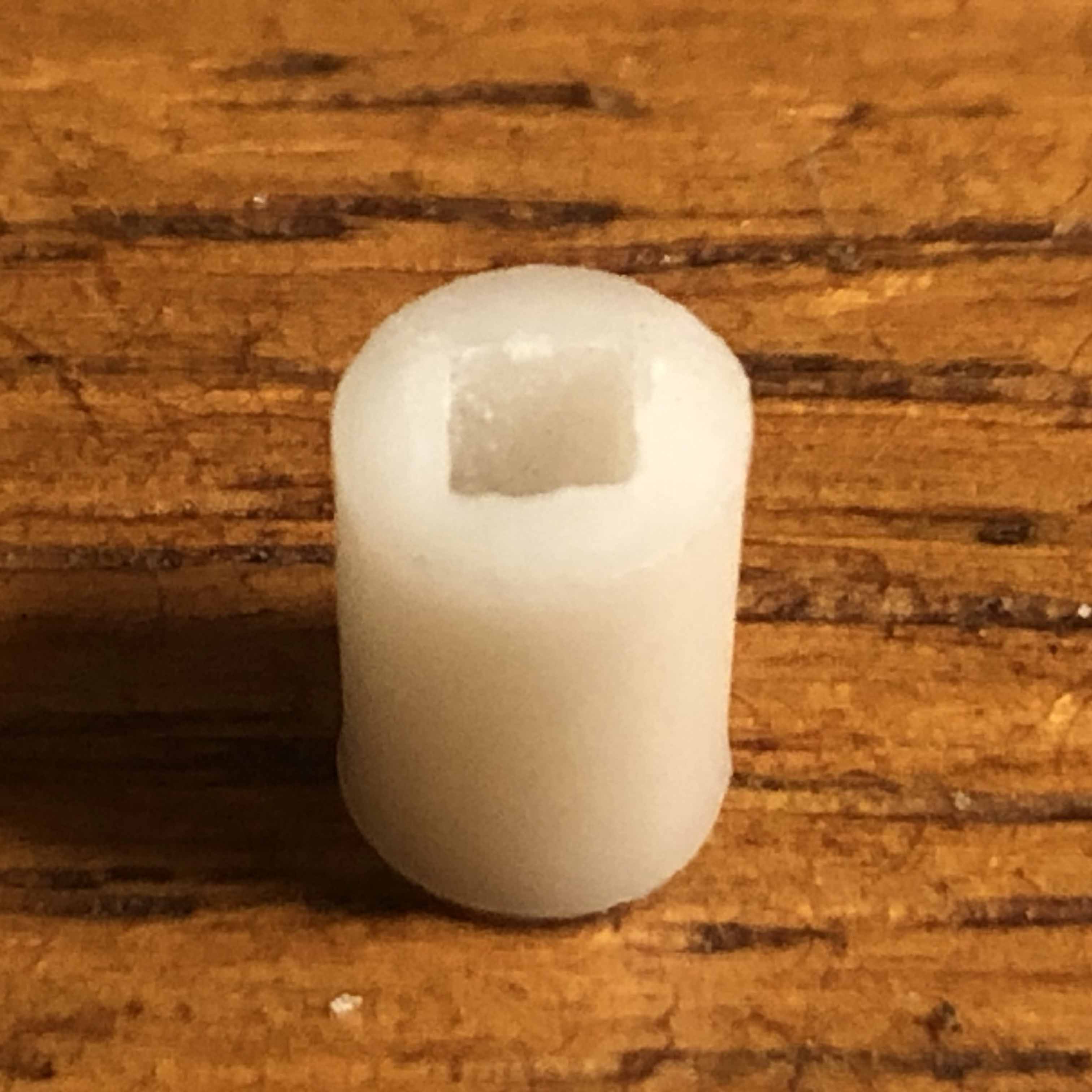
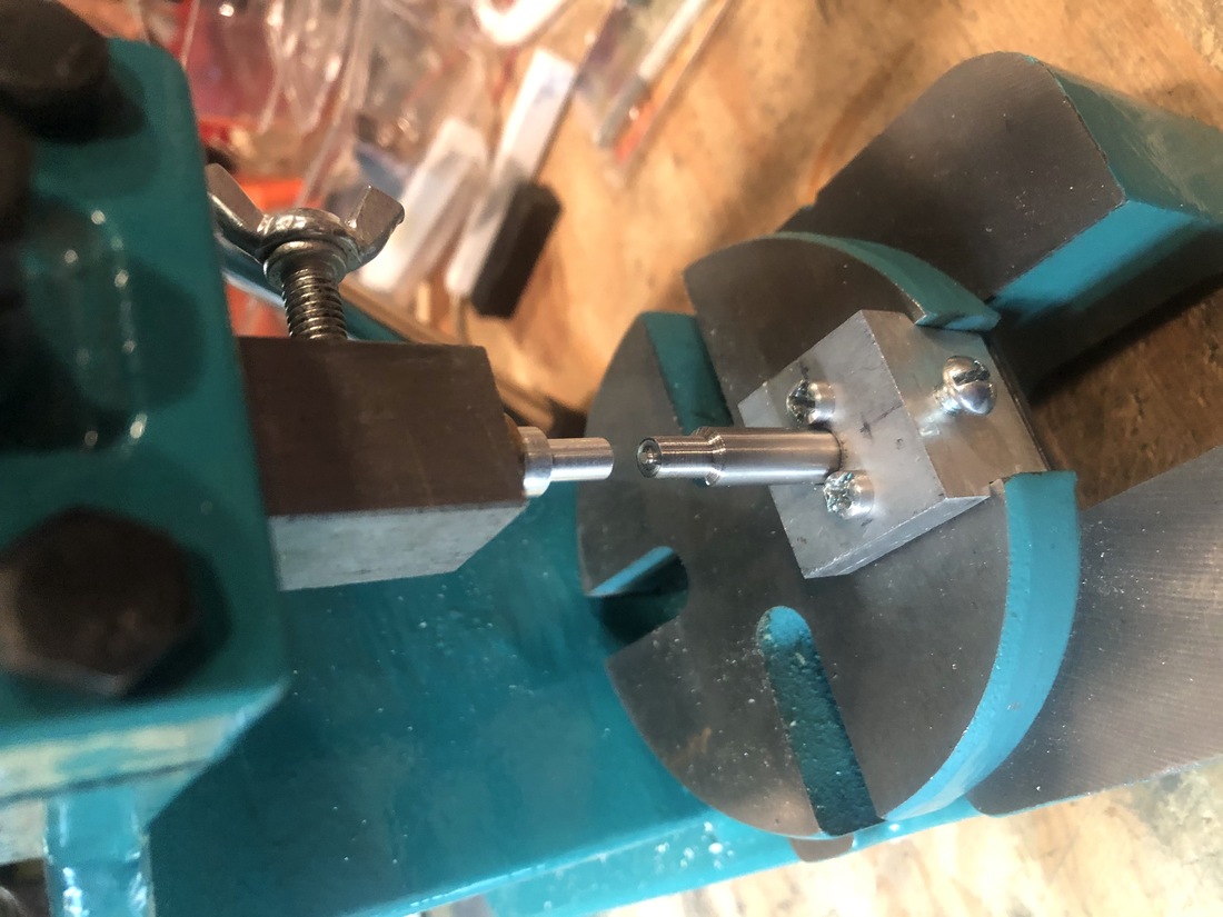
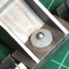
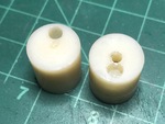
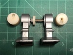
The drive cleat can be replaced without any disassembly or as part of the replacement of the drive gear. Either way, the trick is to press it onto the axle only halfway. I've mostly only done this when replacing the drive gear so I use this little tool I made using a mill bit to set a 5/32" hole with a nail in the middle to limit the axle from going all the way to the bottom of the piece. Otherwise, just carefully press it on.
- top
Although Billy and Robbie have two batteries, they are setup in parallel which means the circuit is still only 1.5 Volts. So the lamp needs to be 1.5 Volts as well. Unfortunately the 1.5V micro lamps I've found really aren't as bright as the originals - but they work.
- Unsolder the lamp leads from the motor on each side.
- Cut the new lamp leads to the same length as the old.
- Solder each lamp lead. You may be able to do this with the existing solder or add some as needed.
Note that these lamps can also be used for any of the lighted accessories.
- top
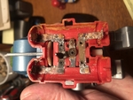
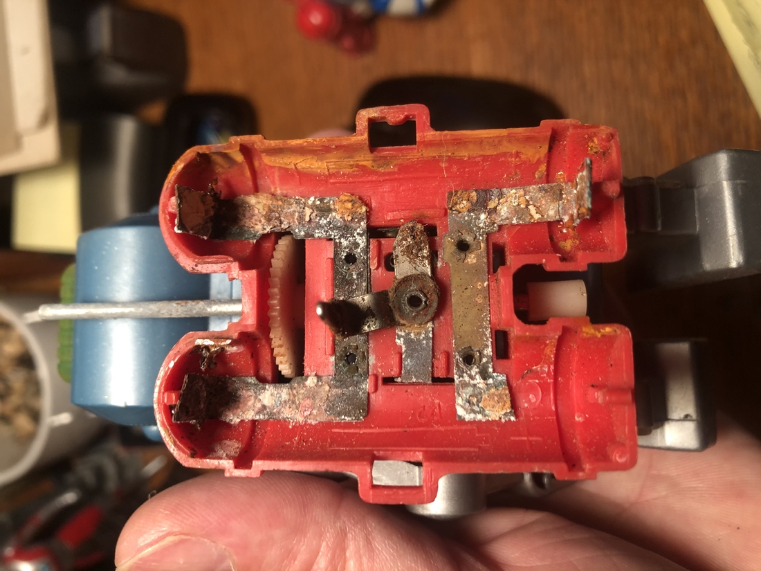
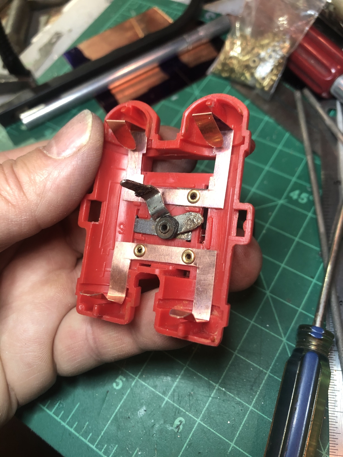
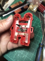
Battery traces can become corroded and broken. I recently took one on that was pretty far gone to see if I could make the new replacement and work with those tiny rivets. Research showed that the springy copper used for battery traces is Beryllium Copper. I couldn't find any of that in small quatities so I went with a regular sheet of .2mm thick copper. I suspect it was easier to cut than the more springy stuff. I was able to cut it with the thick hobby knife and a straight edge. The rivets needed are 2mm x 4mm and the proper tubular rivet peening tool. Since the rivets are through plastic, you don't want to bacng them with a hammer. You need to workout a way to apply steady pressure without an impact. I use a small arbor press with a modified peening tool and a custom made backing die. I'm not sure what else would work. You'll have to improvise on this one.
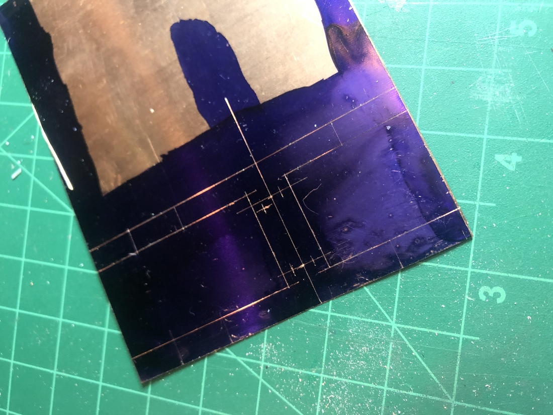
Make the new traces
- Measure the previous traces and transfer those measurements to the sheet copper. Since the measurements are pretty critical, best to use blue layout fluid and a scriber or the back edge of a hobby knife.
- Set the holes for drilling with the point of a sharp nail.
- Drill both holes with a 3/32" drill bit.
- Cut traces out using a straight edge and a hobby knife.
- Use a hobby knife to clean up the edges of the new copper piece.
Remove old trace
- Use a small drill bit to remove the head of each rivet on the trace side.
- Push the rivets out and remove the old
Install new traces
- Test fit the new traces and make sure that the holes line up properly by slipping each rivet through the trace and Jet Pack holes.
- If there are any adjustments needed make them before any rivet is installed.
- Install each rivet using your peening tool such that the peening is done on the non-visible side.


- top
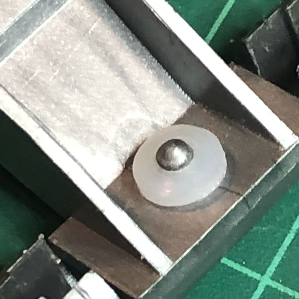
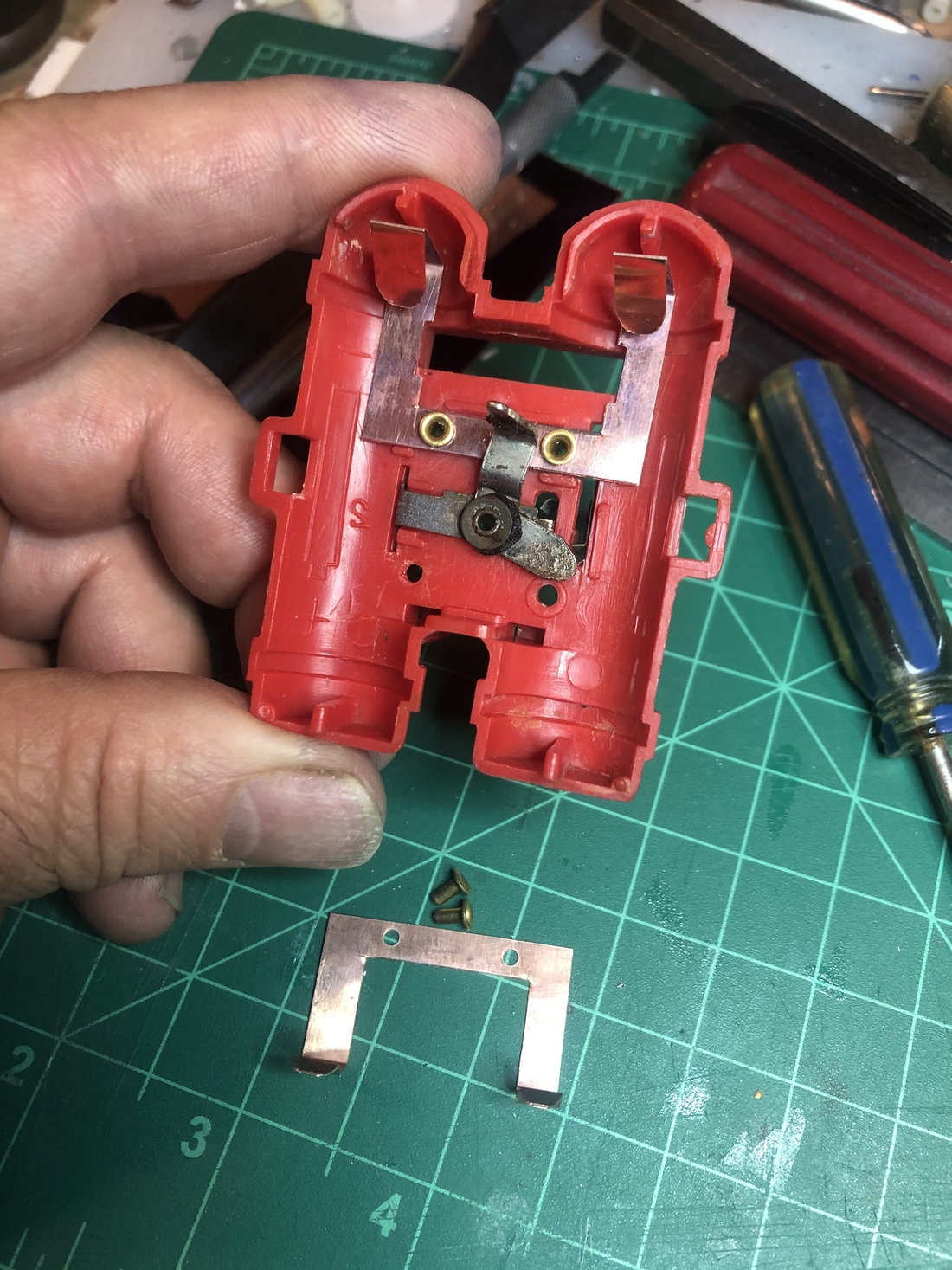
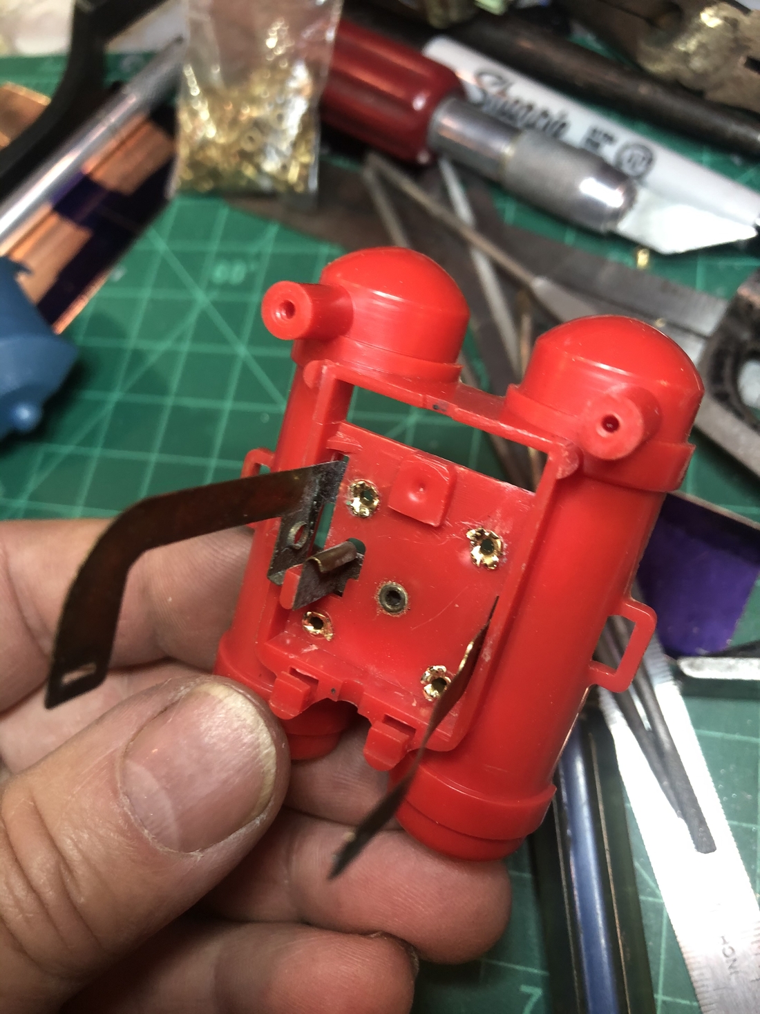
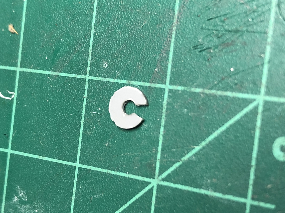
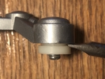
I have repaired a few switches on the gen 1 Billy and Robbies but haven't had to do any on the gen 2. The main thing has been when the switch is loose it is no longer making a good electrical contact with the trace it is mounted to. Usually this has to do with the rubber washer becoming hard or being gone altogether. I've used my arbor press to do a very gentle tightening in couple recent cases and previous to that I've created small plastic U shaped plates and slipped it where the washer used to be. Now that I've got a setup for these little rivets I will probably seek out some replacement rbber washers and just replace the rivet and washer. You can probably do something like this with a C-clamp if needed. Just don't bang on a rivet since it will likely break the plastic of the Jet Pack.

- top
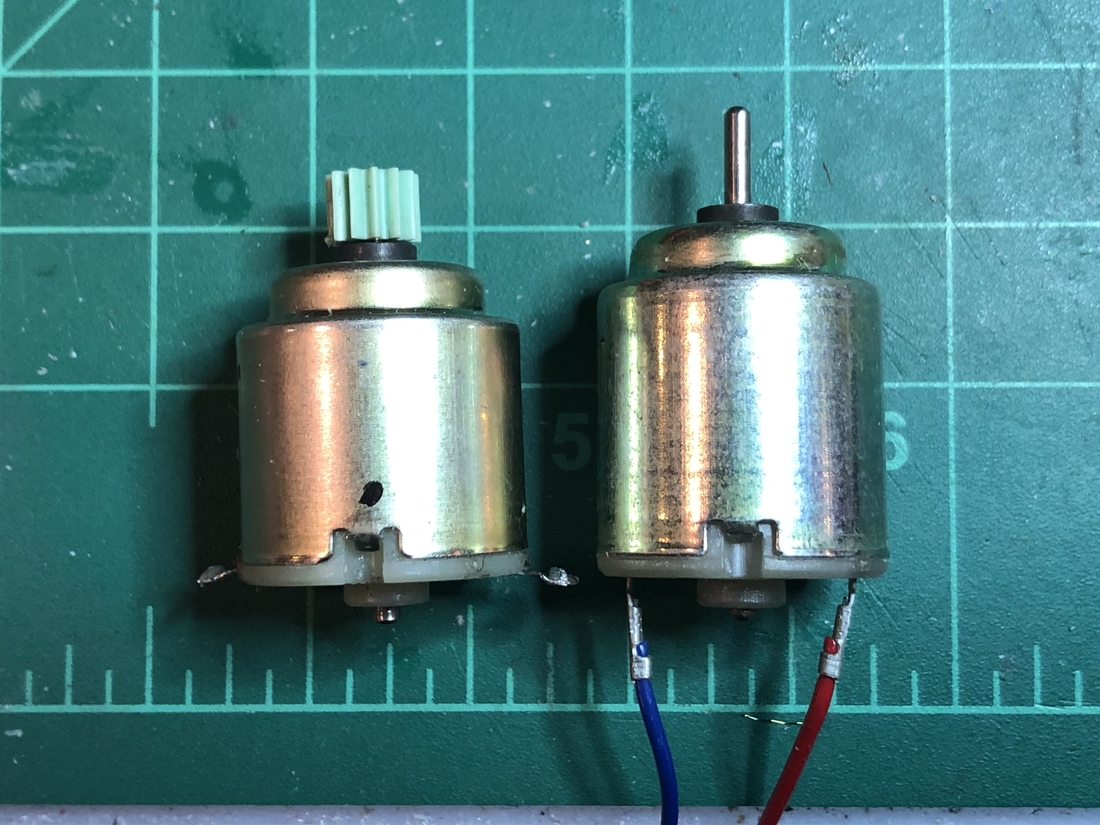
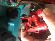
I've had a few motors that seemed shot but a pretty simple rebuild has saved each of them. Although there are motors out there with the same part number (Mabuchi RE-14) they are a little bigger than the ones in Billy and Robbie. So, rehab is the only option I've found for a bad motor. Although, in one case I replaced the end bell, brushes and brush springs taken from a new RE-14 motor. I am purposely not listing the motor above since it isn't an actual replacement.

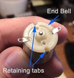

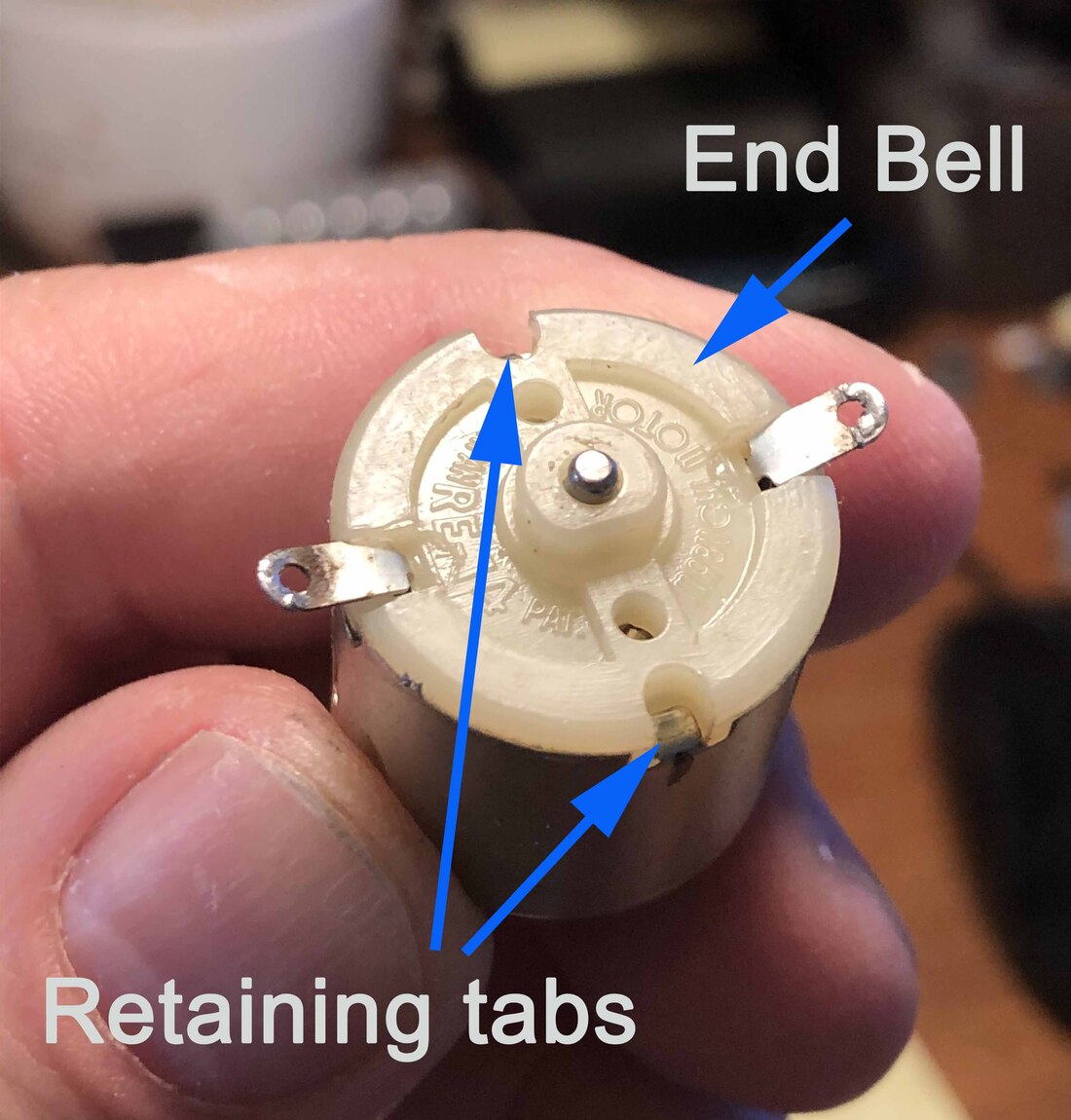
- Mark end bell on the same side and you have marked the body during disassembly.
- Bend back the two retaining tabs.
- Pull the end bell back removing the brushes.
- Carefully clean this part. I like to blast it with brake cleaner myself.
- Make sure the contacts are clean.
- You can put this back together dry but it's best to put a little dielectric grease on the brushes and parks of the axle that makes contact while spinning.
- Insert the assembly back into the body.
- Give the motor a test before bending the retaining tabs back.
- Re-clean if necessary.
- When satisfied with motor's performance, bend retaining tabs back.
- top
- Install the antenna shaft and jet pack.
- Screw jet pack retaining screws back on.
- Install gearbox and solder motor back on making sure the mark you made earlier is the visible.
- Solder light.
- Install leg movement rods, glear leg rings and retaining clips.
- Install arms. If you are using the spring tensioned replcement joing, slip each arm onto the back of the body using a flat head screwdriver, kitchen knife or any other appropriately sized flat piece to make space for the back piece to slip in. IMPORTANT: Do not use the body itself to pry the shoulder joint as the body may break.
- Install legs and front panel.
- Before screwing the body back togehter, test that the motor drives the legs.
- Assuming the walking mechanism now works, screw the fron body panel back on.
- top
- top
Just for fun I took on this basket case Robbie with missing arms and and a broken foot. So in the Japanese Kintsugi tradition of highlighting repairs I made a new foot with a working mechanism pushed by the normal leg rod operation. At some point I'll make some detailed custom arms as well. I've also had in mind to make this one's head turn at some point.


- top
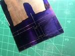
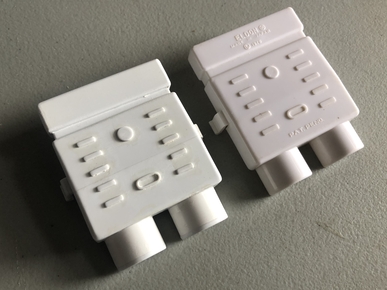
Got tired of waiting for a Gen 2 Billy Jet Pack cover to come up for sale so I made a custom one using Plastruct sheet plastic and tubing.
- top
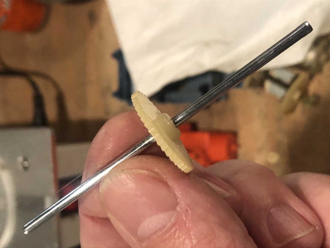
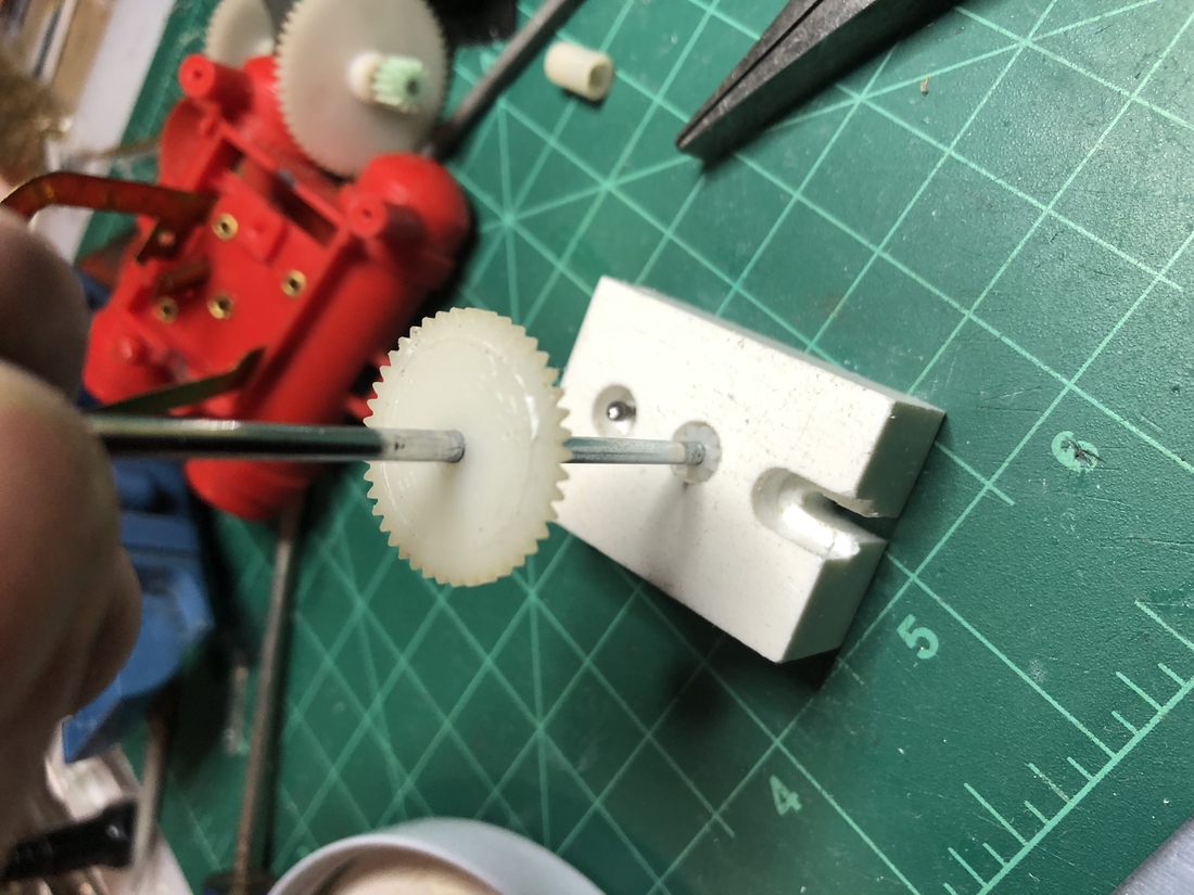
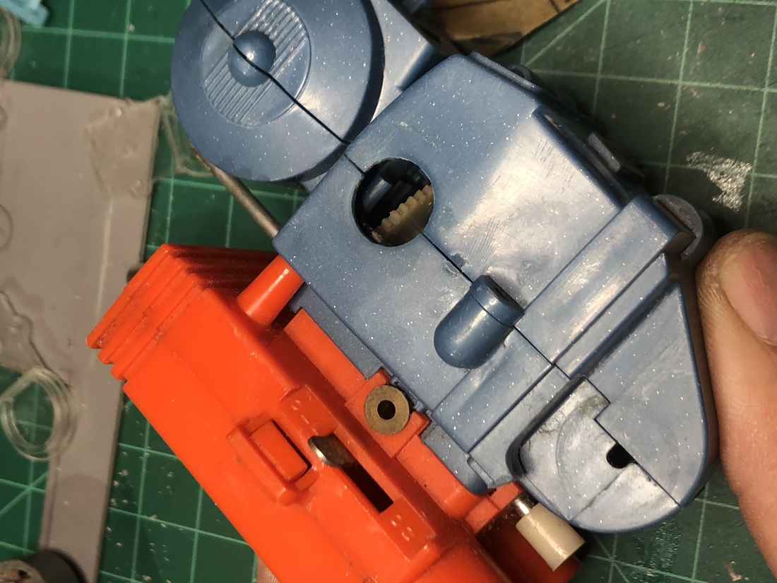
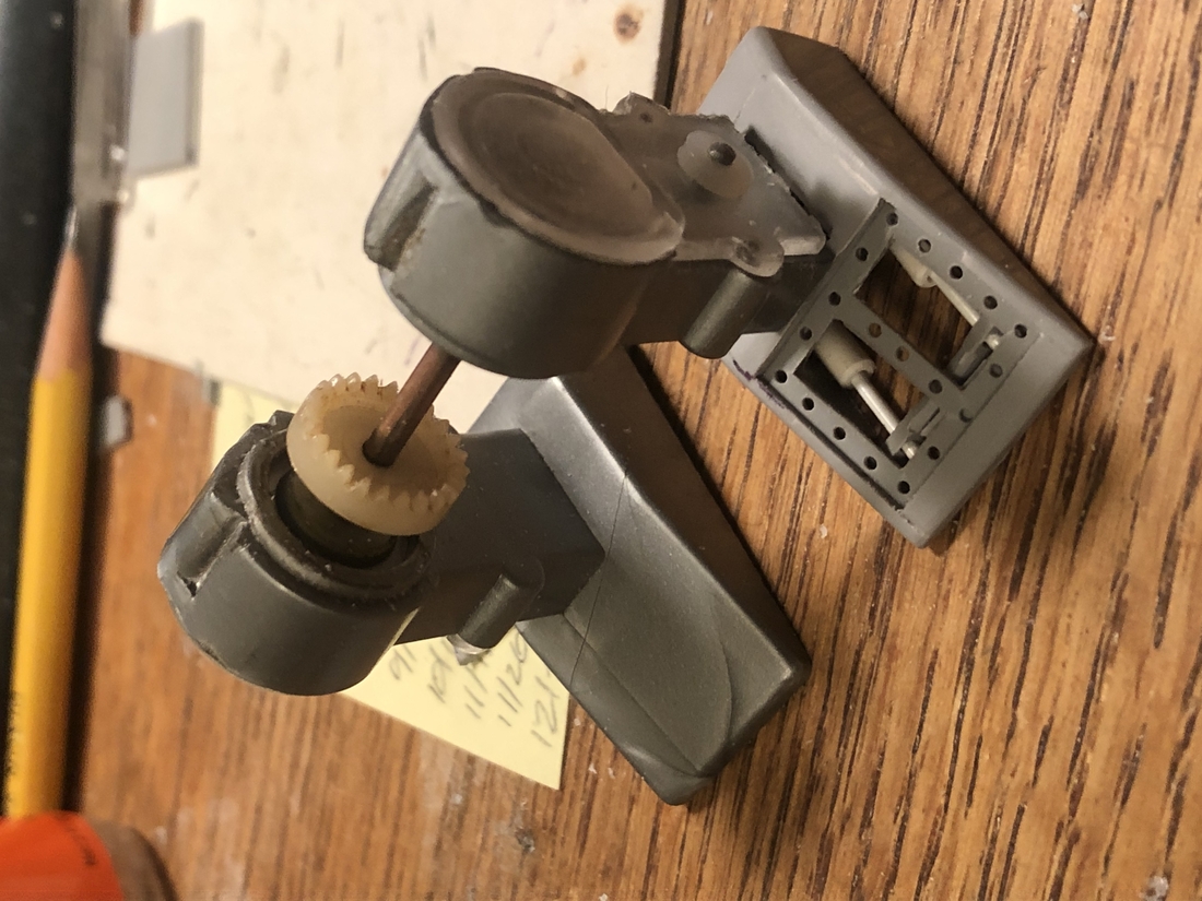
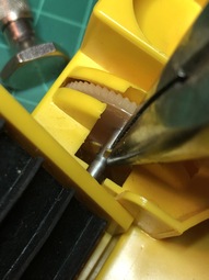
For my first non-space set I purchased a Construction set that was fairly complete but with some issues. I didn't know from the listing that the belt conveyor had a broken gear. No problem since I already had a pack of gears. These are larger than the drive gear in Robbie - 12 tooth and 7mm diameter. Not too difficult to get the part out. The trickiest procedure here is drilling out the little gear. Hard to hold without mangling the gears and it's really easy to get your hole drilled off center if you're not careful. What I ended up doing was just stepping up one numbered drill bit at a time until I got to #35 which made for a nice press fit on the 3mm axle.
- Twist the retaining tab to allow for removal of the lower gear tray.
- Remove screw on the bottom and remove lower gear tray.
- Inspect gear by turing axle and holding gear to see if it is still a tight fit.
- If it is loose, it must be replaced.
- Bend the retaining tab on the lower gear tray to allow for removal of the axle.
- Measure distance of existing gear to end of axle before removing gear. In this case, 5/16".
- Remove gear.
- Drill out replacement gear (12 tooth, 7mm diameter) to #35.
- Press gear onto axle leaving 5/16" of axle showing.
- Spin axle to check for a well centered hole. It can wobble just a little but not too much.
- Reassemble and test running action.

Top
|